Beko HIMW75225 User Manual - Page 11
conversion
 |
View all Beko HIMW75225 manuals
Add to My Manuals
Save this manual to your list of manuals |
Page 11 highlights
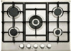
5 23 4 min. 20 & max. 40 mm 1 Hob 2 Screw 3 Installation clamp 4 Counter 5 Putty Rear view (connection holes) Gas conversion ^ DANGER • Before starting any work on the gas installation, disconnect the gas supply. There is the risk of explosion! In order to change your appliance's gas type, change all injectors and make flame adjustment for all valves at reduced flow rate position. Exchange of injector for the burners 1. Take off burner cap and burner body. 2. Unscrew injectors by turning the counter- clockwise. 3. Fit new injectors. 4. Check all connections for secure fitting and tightness. New injectors have their position marked on their packing or injector table on Injector table, page 5 can be referred to. 2 t Place the burner plates, burner plate caps and grills back to their seating after installation. Making connections to different holes is not a good practice in terms of safety since it can damage the gas and electrical system. Final check 1. Open gas supply. 2. Check gas installations for secure fitting and tightness. 3. Ignite burners and check appearance of the flame. Flame must be blue and have a regular shape. If the flame is yellowish, check if the burner cap is seated securely or clean the burner. 3 4 1 Flame failure device (model dependant) 2 Spark plug 3 Injector 4 Burner Unless there is an abnormal condition, do not attempt to remove the gas burner taps. ou must call an Authorised service agent if it is necessary to change the taps. Reduced gas flow rate setting for hob taps 1. Ignite the burner that is to be adjusted and turn the knob to the reduced position. 2. Remove the knob from the gas tap. 3. Use an appropriately sized screwdriver to adjust the flow rate adjustment screw. For LPG (Butane - Propane) turn the screw clockwise. For the natural gas, you should turn the screw counter-clockwiseonce. 11/EN
-
 1
1 -
2
-
3
-
4
-
5
-
 6
6 -
 7
7 -
 8
8 -
 9
9 -
 10
10 -
 11
11 -
 12
12 -
 13
13 -
 14
14 -
 15
15 -
 16
16 -
17
-
18
-
19
-
20
 |
 |
