Belkin F6C150-RKM-2U Belkin OmniGuard Rackmount UPS Hardware Manual - Page 10
Alarms, Communications Port
 |
View all Belkin F6C150-RKM-2U manuals
Add to My Manuals
Save this manual to your list of manuals |
Page 10 highlights
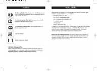
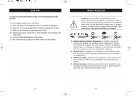
PRODUCT DIAGNOSTICS Alarms ON-BATTERY When the UPS is operating on the batteries, the On-Line LED will blink and the audible alarm will sound every 10 seconds. The alarm will stop once the UPS returns to On-Line operation. UPS FAULT When the UPS detects a hardware fault, the Fault LED will illuminate and the UPS will emit a sustained tone. The fault condition can be reset by turning the UPS OFF and then ON. OVERLOAD When the amount of load attached to the UPS exceeds its power rating, the Overload LED will illuminate and the UPS will emit a sustained tone. This alarm will remain on until the excess load is removed or the UPS self-protection circuit shuts the UPS down. REPLACE BATTERY The UPS automatically tests the battery condition and will illuminate the Weak/Bad Battery LED and emit a short beep. This tone will be repeated every hour until the battery passes a self-test. It is recommended that the UPS be allowed to charge overnight before performing a battery test to confirm a Weak/Bad Battery condition. LOW-BATTERY WARNING The UPS will emit two consecutive beeps every five seconds when the battery reserve runs low. This continues until AC returns or the UPS shuts down from battery exhaustion. PRODUCT DIAGNOSTICS Communications Port The communications port is a standard DB9 female with both RS232 and simulated contact closure capability. The OmniGuard units will poll the port and activate it for RS232 or contact closure in accordance with the type of cable it finds connected to the port. Changing the port configuration requires that the unit be turned off and restarted with the desired cable connected. The pin-out for the port is depicted below. DB9 Standard Pin-Out: Pin 1: Battery low Pin 2: /TXD Pin 3: /RXD Pin 4: UPS shutdown Pin 5: Ground Pin 6:Instant off (Pull and hold this pin low to turn off the UPS. Release this pin from low to restart the UPS.) Pin 7: Not used Pin 8: AC fail signal Pin 9:ATX wake-up signal 18 19
-
 1
1 -
2
-
3
-
4
-
 5
5 -
 6
6 -
 7
7 -
 8
8 -
 9
9 -
 10
10 -
 11
11 -
 12
12 -
 13
13 -
 14
14 -
 15
15 -
16
-
17
 |
 |
