Belkin F6C1500-TW-RK User Manual - Page 1
Belkin F6C1500-TW-RK Manual
 |
View all Belkin F6C1500-TW-RK manuals
Add to My Manuals
Save this manual to your list of manuals |
Page 1 highlights
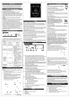
INTRODUCTION Thank you for purchasing a Belkin Uninterruptible Power Supply (UPS). Each year, several natural and man made occurrences put the power supplied to your electronics in your home or office in jeopardy. At risk are your hardware, software and data because of these power problems. IMPORTANT SAFETY INSTRUCTIONS Please save this manual! It contains important operating instructions and warranty information pertaining to your UPS. Please save or recycle the packaging materials! The UPS packaging was designed with great care to provide protection during shipment and delivery. These materials are invaluable if you ever have to return the UPS for service. Damage sustained during transit is not covered under the warranty. Federal Communications Commission Interference Statement This equipment has been tested and found to comply with the limits for a Class B digital device, pursuant to Part 15 of the FCC Rules. These limits are designed to provide reasonable protection against harmful interference in a residential installation. This equipment generates, uses and can radiate radio frequency energy and, if not installed and used in accordance with the instructions, may cause harmful interference to radio communications. To assure continued compliance, use only shielded interface cables when connecting to computer or peripheral devices. Any changes or modifications not expressly approved by the party responsible for compliance could void the user's authority to operate this equipment. UPS FEATURES AND FUNCTIONS FRONT PANEL fig. 1 ON/ OFF/ TEST ON LINE ON BATTERY FAULT/ * OVERLOAD/ * REPLACE BATTERY Your UPS features 3 LED indicators which specific's certain functions on your UPS. Please review the Front Panel diagram and with this chart, as it will assist you in the use of your UPS. Indicator Condition Meaning ON LINE О Solid Green AC Power is on (Green LED) ☼ Flashing Green AVR is active This condition for the On-Battery LED can indicate 1 of 2 problems: ON BATTERY ☼ Flashing Yellow 1. The UPS is backup and on an battery intermittent LED with Audible audible alarm is on. The UPS (Yellow LED) Alarm (Beeping) will begin shutdown procedure. 2. Battery is low. The UPS will start shutdown. The buzzer sounds an audible alarm. FAULT/ *OVERLOAD/ *Replace Battery (Red Led) ○ Solid Red The Fault/Overload can indicate 1 of 2 problems. 1. There is a problem with the UPS. The LED will be lit continuously, and the unit will sound an audible alarm for 10 seconds. 2. Battery is weak or bad; the battery needs to be replaced. ☼ Flashing Red Battery output is drawing more power than the UPS can provide. SITE WIRING FAULT (ON REAR PANEL) ○ Solid Red There is either no ground circuit or a reversed polarity in the building wiring. BATTERY REPLACEMENT PROCEDURE Replacement requires removing the battery cover plate on the front of the UPS. No tools are needed. To replace the batteries: 1. Press fastener to remove the battery cover plate on the front of the UPS (Fig. 1 & 2). 2. Disconnect the insulated connectors from the battery terminals (Fig. 3 & 4). 3. Remove the battery then insert a new battery pack, and push the connectors onto the battery terminals (black to black & red to red) (Fig. 3 & 4). NOTE: There may be a small spark at the battery terminals when reconnecting the connectors. This is normal and will not harm you or the UPS. 4. Close the battery cover (Fig. 1). Fig. 1 Fig. 2 Fig. 3 for Model: F6C1500-TW-RK Fig. 4 for Model: F6C1000-TW-RK F6C1250-TW-RK ○R FOR MODEL F6C1000-TW-RK F6C1250-TW-RK F6C1500-TW-RK ALARMS BATTERY BACK UP (Slow Alarm) When in the UPS is in battery BACK-UP mode, the On Battery (Yellow LED) illuminates and the UPS sounds an audible alarm. The alarm stops when the UPS returns to normal ON LINE operation. LOW BATTERY (Rapid Alarm) When the UPS is in battery BACK-UP mode and the battery energy begins to run low, the UPS will beep rapidly until it shuts down from a depleted battery or returns to ON LINE normal operation. OVERLOAD (Continuous alarm) When the UPS is overloaded (the connected loads exceed the maximum rated capacity), the UPS emits a continuous alarm to warn of an overload condition. Disconnect nonessential equipment. from the UPS to eliminate the overload. FAULT (10 Seconds Continuously) When the UPS occur fault, the UPS emits a 10 seconds continuous alarm to warn of a fault condition. Disconnect the equipment from the UPS prior to checking the equipment. To Silence Audible Alarm While in battery BACK-UP mode, push on/off/test button less than 1.5 seconds to silence the audible alarm. (This does not work if the UPS is under LOW BATTERY or OVERLOAD condition. REAR PANEL REAR PANEL fig. 2 G H CB F A ED A、 BATTERY BACK UP SURGE PROTECTION OUTLETS Only data sensitive equipment such as a computer, monitor and external drive should be plugged into these outlets. Battery power is automatically provided in case of a power outage. Power (AC or battery) is not supplied to these outlets when the UPS is switched off. (Do not plug surge protectors or power strips into the battery back up outlets). Note! During the AVR Mode, the total load that you will be placing on the battery back up outlets should not exceed 80% of the unit's capacity. B、 PHONE/FAX/ MODEM PROTECTION The phone/fax/modem lines are surge protected and provide complete safety for line connection. C、 INTERFACE PORTS (USB & RS232) The UPS provides both a USB and RS232 port for use with your computer. NOTE: Choose one port only. D、 AC INPUT BREAKER (CIRCUIT BREAKER) The circuit breaker button will be triggered if an overload condition forces the UPS to disconnect itself from utility power. If the button sticks out, disconnect nonessential equipment and depress breaker. E、 AC INPUT POWER CORD F、 SITE WIRING FAULT INDICATOR The Site Wiring Fault LED will illuminate when one of the following conditions exist: 1. Open or high-resistance ground 2. Hot and neutral polarity reversal 3. Overloaded neutral circuit G、 NETWORK PROTECTION This connector is used for protecting the transmission line of Ethernet card from surge, noise and spike. H、 ACCESSORY SLOT Optional SNMP Slot CONTENTS You should have received the following: 1 - UPS unit 1 - Bulldog Plus Shutdown Software 1 - USB Cable 1 - Serial Cable 1 - Phone Line Cable INSTALLATION Note! Before installation, please inspect the UPS Upon receipt. Make sure that the UPS is not damaged. Connect to AC Utility Power Connect the AC inlet to utility power via the power cord. Check whether the Site Wiring Fault indicator is lit or not. If so, please check the utility wiring. Charging the Battery For best results, charge the battery for 8 hours prior to initial use. The UPS charges its battery whenever it is connected to the utility power. Plug in Power Devices Plug your devices into the AC outlets on the rear of the UPS. To use the UPS as a master on/off switch, make sure all of the loads are switched on. Caution: Never connect a laser printer or scanner to the backup outlets of UPS with other computer equipment. A laser printer or scanner draws significantly more power when in use than when idle. This may overload the UPS. Laser Printer Turning on the UPS Turn on your UPS by pressing and holding the On/Off/Test button for approximately 2 seconds until the "ON LINE" Green comes on. Turning off the UPS Turn off the UPS by pressing and holding the On/Off/Test button for more than 2 seconds until the "ON LINE" or "ON BATTERY" LED goes off. To Conduct a Self Test Use the self-test to verify both the operation of the UPS and the condition of the battery. In normal utility power, push the On/Off/Test button less than 1.5 seconds and the UPS performs a self-test function. During the self-test, the UPS operates in back-up mode. Note! During the self-test, the UPS briefly operates onbattery backup power (the on-battery LED comes on). If the UPS passes the self -test, it returns to on-line operation. If the UPS fails the self-test, it immediately returns to on-line operation and lights the replace battery LED. The loads are not affected. Recharge the battery overnight and perform the self- test again. If the replace battery LED is still on, the battery will need to be replaced. Connect the phone/ fax/ modem/ lines Connect a single phone/ fax/ modem line into the surge-protected sockets on the back of the UPS. The RJ-11 modular sockets accepts standard single line telephone connections. The connection will require another length of telephone cable, which is supplied. Note! This connection is optional but highly suggested as phone/ fax/modem lines often carry dangerous surges and spikes. The UPS works properly without a phone/ fax/ modem connection. Caution! The phone/ fax/modem protection feature could be rendered inoperable if improperly installed. Make sure that the telephone line from the wall is plugged into the connector marked "IN", and the device to be protected is plugged into the connector marked " OUT". Connect the Network Protection Lines Connect the network line from the wall to the connector marked "IN", then connect the device (Ethernet card) to be protected to the connector marked "OUT". * All equipment must be turned off prior to hardware installation. SYSTEM REQUIREMENTS The UPS can be used without the software and can be used with any computer using a monitor or a flat panel screen. Also, you do not have to have the software installed to utilize the battery backup outlets. To fully utilize the UPS and its software, your computer must be able to operate the following operating systems: 95/ 98/ ME/ NT4/ 2000/ 2003/ XP & Linux & Higher and have a Serial or USB port. SERIAL OR USB COMMUNICATION PORT (INSTALLATION OPTIONAL) To fully utilize the Bulldog Plus Shutdown Software; you will need to connect the UPS to your computer. The communication port will provide the following features: 1. Monitoring charger status 2. Monitoring UPS status 3. Monitoring battery status and condition 4. Monitoring the utility status 5. Use the ON/OFF/TEST UPS power switch function to schedule UPS for power saving
-
 1
1 -
 2
2
 |
 |