BenQ 0.6 Wall Mount Wall Mount User Manual - Page 2
Introduction, Required Tools, Installation Steps, Packaged Parts, Specifications/Size/Guide sheet - wall mount 0 6
 |
View all BenQ 0.6 Wall Mount manuals
Add to My Manuals
Save this manual to your list of manuals |
Page 2 highlights
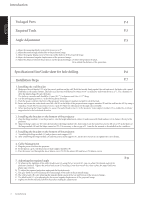
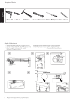
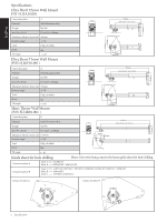
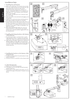
Introduction English Packaged Parts P.4 Required Tools P.5 Angle Adjustment P.5 1. Adjust the mounting bracket arm of the projector to 5°. 2. Adjust the rotation angle of the sides of the projected image. 3. Adjust the angular displacement of the top and the bottom of the projected image. 4. Adjust the horizontal angular displacement of the projected image. 5. Adjust the distance between the projector and the projected image: (A) Move the projector bracket. (B) or adjust the distance of the projection. Specifications/Size/Guide sheet for hole drilling P.6 Installation Steps P.7 1. Installing the wall bracket A. Make sure the wall bracket (O) is in the correct position on the wall. Hold the bracket firmly against the wall and mark the holes with a pencil. Drill holes at the marked points. The holes in a masonry wall should be 10mm (0.39") in diameter and 55mm deep (2.17"). Use a hammer to drive the plastic plugs (B) into the holes. The holes in a wooden wall should be 4.5mm (0.17") in diameter and 55m (2.17") deep. B. Use the self-tapping screws (C) to fix the bracket to the wall. C. Push the power cord into the front of the projector main support member and pull it out at the back. D. Insert and secure the socket head screw M6 x L8 (E) in the holes of the projector main support member (P) and the wall bracket (O) by using a 5mm hex wrench (K). It is necessary to leave a gap of 0.5mm for adjustment of the angle after assembly. E. Before positioning the hinge module (A), secure the socket head screw (G) in the projector main support member (P) to enable the cantilever support to be in the horizontal direction. 2. Installing the bracket on the bottom of the projector A. Place the hinge module (A) on the projector. Use the height adjustment collars (I) and screws with fixed washers (H) to fasten it firmly to the projector. B. Align the hinge connector (D) with the hole above the hinge module (A). Insert and secure the socket head screw M6 x L12 (F) in the holes of the hinge module (A) and the hinge connector (D). It is necessary to leave a gap of 2-3 mm for the support to be installed on the cantilever. 3. Installing the bracket on the bottom of the projector. A. Assembling the hinge module (A) and projector main support (P). B. After assembling the hinge module (A) and the project main support (P), use the hex wrench (K) to tighten the screws firmly. 4. Cable Management A. Plug the power cord into the projector. B. Fit the plastic cap (L) on the projector main support member (P). C. Pass the power cord through the lower plastic cover (N). Fit the upper (M) and lower (N) plastic covers. 5. Adjusting the required angle A. By adjusting the tightness of the socket head screw (G) using the hex wrench (K), you can adjust the desired angle of the projector cantilever. Tighten the socket head screw (E) by using a 5mm hex wrench (K), then replace the upper and lower plastic caps (M)(N). B. To adjust the required projection angle push the knobs inwards. C. The gray knob (A) is for adjusting the rotation angle of the sides of the projected image. D. The yellow knob (B) is for adjusting the angular displacement of the top and bottom of the projected image. E. The black knob (C) is for adjusting the horizontal angular displacement of the projected image. F. Tighten the knobs well and pull them back after making the adjustments. P.8 3 Introduction
-
 1
1 -
 2
2 -
 3
3 -
 4
4 -
 5
5 -
 6
6 -
 7
7
 |
 |