Biostar A740GM2 Bios Setup
Biostar A740GM2 Manual
 |
View all Biostar A740GM2 manuals
Add to My Manuals
Save this manual to your list of manuals |
Biostar A740GM2 manual content summary:
- Biostar A740GM2 | Bios Setup - Page 1
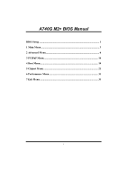
A740G M2+ BIOS Manual BIOS Setup 1 1 Main Menu 3 2 Advanced Menu 6 3 PCIPnP Menu 16 4 Boot Menu 19 5 Chipset Menu 21 6 Performance Menu 31 7 Exit Menu 33 i - Biostar A740GM2 | Bios Setup - Page 2
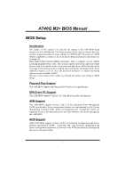
A740G M2+ BIOS Manual BIOS Setup Introduction The purpose of this manual is to describe the settings in the AMI BIOS Setup program on this motherboard. The Setup program allows users to modify the basic system configuration and save these settings to CMOS RAM. The power of CMOS RAM is supplied - Biostar A740GM2 | Bios Setup - Page 3
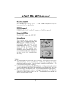
A740G M2+ BIOS Manual PCI Bus Support This AMI BIOS also supports Version 2.3 of the Intel PCI (Peripheral Component Interconnect) local bus specification. DRAM Support DDR2 SDRAM (Double Data Rate II Synchronous DRAM) is supported. Supported CPUs This AMI BIOS supports the AMD CPU. Using Setup - Biostar A740GM2 | Bios Setup - Page 4
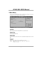
A740G M2+ BIOS Manual 1 Main Menu Once you enter AMI BIOS Setup Utility, the Main Menu will appear on the screen providing an overview of the basic system information. Main Advanced BIOS SETUP UTILITY PCIPnP Boot Chipset Performance Exit System Overview AMI BIOS Version :01.01.01 Build Date: - Biostar A740GM2 | Bios Setup - Page 5
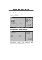
A740G M2+ BIOS Manual IDE Configuration The BIOS will automatically detect the presence of IDE/SATA devices. There is a sub-menu for each IDE/SATA device. Select a device and press to enter the sub-menu of detailed options. Main IDE Confuguration > Primary IDE Master > Primary IDE Slave > - Biostar A740GM2 | Bios Setup - Page 6
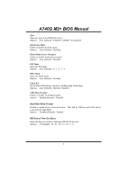
A740G M2+ BIOS Manual Type Select the type of the IDE/SATA drive. Options: Auto (Default) / CDROM / ARMD / Not Installed LBA/Large Mode Enable or disable the LBA mode. Options: Auto (Default) / Disabled Block (Multi-Sector Transfer) Enable or disable multi-sector transfer. Options: Auto (Default) / - Biostar A740GM2 | Bios Setup - Page 7
A740G M2+ BIOS Manual 2 Advanced Menu The Advanced Menu allows you to configure the settings of CPU, Super I/O, Power Management, and other system devices. Notice z Beware of that setting inappropriate values in items of this menu may cause system to malfunction. Main Advanced BIOS Option F1 - Biostar A740GM2 | Bios Setup - Page 8
A740G M2+ BIOS Manual Secure Virtual Machine Mode Virtualization Technology can virtually separate your system resource into several parts, thus enhance the performance when running virtual machines or multi interface systems. Options: Enabled (Default) / Disabled PowerNow This item allows you to - Biostar A740GM2 | Bios Setup - Page 9
A740G M2+ BIOS Manual Link Width Options: Auto (Default) / 8 Bit / 16 Bit CPU FID/VID Control Advanced CPU FID/VID Control BIOS SETUP UTILITY Processor Multiplier Processor Voltage [Auto] [Auto] Options Select Screen Select Item +- Change Option F1 General Help F10 Save and Exit ESC Exit vxx - Biostar A740GM2 | Bios Setup - Page 10
A740G M2+ BIOS Manual SuperIO Configuration Advanced BIOS SETUP UTILITY Configure ITE8718 Super IO Address This item allows you to determine access onboard parallel port controller with which I/O Address. Options: 378 (Default) / 278 / 3BC / Disabled Parallel Port Mode This item allows you - Biostar A740GM2 | Bios Setup - Page 11
A740G M2+ BIOS Manual Parallel Port IRQ This item allows you to select the IRQ for the onboard parallel port. Options: IRQ7 (Default) / IRQ5 / Disabled Keyboard PowerOn This item allows you to control the keyboard power on function. Options: Disabled (Default) / Enabled Mouse PowerOn This item - Biostar A740GM2 | Bios Setup - Page 12
A740G M2+ BIOS Manual CPU Smart Fan This item allows you to control the CPU Smart Fan function. Options: Disabled (default) / Auto / 4-pin / 3-pin Smart Fan Calibration Choose this item and then the BIOS will auto test and detect the CPU/System fan functions and show CPU/System fan speed. Control - Biostar A740GM2 | Bios Setup - Page 13
A740G M2+ BIOS Manual Hardware Health Configuration This item shows the system temperature, fan speed, and voltage information. Advanced BIOS 12.0V DDR Voltage HT Voltage 5VSB VBAT Select Screen Select Item +- Change Option F1 General Help F10 Save and Exit ESC Exit vxx.xx (C)Copyright 1985- - Biostar A740GM2 | Bios Setup - Page 14
A740G M2+ BIOS Manual Power Configuration Advanced BIOS SETUP UTILITY ACPI Settings Suspend mode ACPI Version Features ACPI APIC support AMI OEMB table Headless mode of ACPI. Options: ACPI v1.0 (Default) / ACPI v2.0 ACPI APIC support This item is used to enable or disable the motherboard's APIC - Biostar A740GM2 | Bios Setup - Page 15
A740G M2+ BIOS Manual Headless mode This is a server-specific feature. A headless server is one that operates without a keyboard, monitor or mouse. To run in headless mode, both BIOS and operating system (e.g. Windows Server 2003) must support headless operation. Options: Disabled (Default) / - Biostar A740GM2 | Bios Setup - Page 16
A740G M2+ BIOS Manual USB 2.0 Controller Mode This item allows you to select the operation mode of the USB 2.0 controller. Options: HiSpeed (Default) USB 2.0-480Mbps FullSpeed USB 1.1-12Mbps BIOS EHCI Hand-Off This item allows you to enable support for operating systems without an EHCI hand- - Biostar A740GM2 | Bios Setup - Page 17
A740G M2+ BIOS Manual 3 PCIPnP Menu This section describes configuring the PCI bus PCI Resource > PCI Express Configuration Clear NVRAM during System Boot. Select Screen Select Item +- Change Option F1 General Help F10 Save and Exit ESC Exit vxx.xx (C)Copyright 1985-200x, American Megatrends, - Biostar A740GM2 | Bios Setup - Page 18
A740G M2+ BIOS Manual PCI Latency Timer This item controls how long a PCI device can hold the PCI bus before another takes over. The longer the latency, the longer the PCI device can retain control of the bus before handing it over to another PCI device. Options: 64 (Default) / 0-255 Allocate IRQ - Biostar A740GM2 | Bios Setup - Page 19
A740G M2+ BIOS Manual IRQ3/4/5/7/9/10/11/14/15 These items will allow you to assign each system interrupt a type, depending on the type of device using the interrupt. The option "Available" means the IRQ is going to assign automatically. Options: Available (Default) DMA Channel 0/1/3/5/6/7 These - Biostar A740GM2 | Bios Setup - Page 20
A740G M2+ BIOS Manual 4 Boot Menu This menu allows you to setup the system boot options. Main Advanced BIOS SETUP UTILITY PCIPnP Boot Chipset Performance Exit Boot Settings Configuration > Boot Device Priority > Hard Disk Drives > Removable Drives > CD/DVD Drives Quick Boot AddOn ROM - Biostar A740GM2 | Bios Setup - Page 21
A740G M2+ BIOS Manual CD/DVD Drives The BIOS will attempt to arrange the CD/DVD drive boot sequence automatically. You can also change the booting sequence. The number of device items that appears on the screen depends on the number of devices installed in the system. Options: Pri. Master / Pri. - Biostar A740GM2 | Bios Setup - Page 22
A740G M2+ BIOS Manual 5 Chipset Menu This submenu allows you to configure the specific features of the chipset installed on your system. This chipset manage bus speeds and access to system memory resources, such as DRAM. It also coordinates communications with the PCI bus. Main Advanced BIOS - Biostar A740GM2 | Bios Setup - Page 23
A740G M2+ BIOS Manual Memory Configuration Memory Configuration Bank Interleaving Channel Interleaving Enable Clock to All DIMMs MemClk Tristate C3/ATLVID Memory Hole Remapping Unganged Mode support Power Down Enable Power Down Mode BIOS function in C3 Mode. Options: Disabled (Default) / Enabled - Biostar A740GM2 | Bios Setup - Page 24
A740G M2+ BIOS Manual Unganged Mode Support This item controls the DRAM controller ganged (128bit*1) / unganged (64bit*2) dual-channel operation mode. If two DRAM modules with different size are installed, using unganged mode can still make it run in dual-channel operation. Options Change Option F1 - Biostar A740GM2 | Bios Setup - Page 25
A740G M2+ BIOS Manual 4-bit ECC Mode Options: Disabled (Default) / Enabled DRAM BG Scrub/Data Cache BG Scrub/L2 Cache BG Scrub/L3 Cache BG Scrub Options: Disabled (Default) DRAM Timing Configuration DRAM Timing Configuration Memory Clock Mode DRAM Timing Mode BIOS SETUP UTILITY Chipset [Auto] [ - Biostar A740GM2 | Bios Setup - Page 26
A740G M2+ BIOS Manual SouthBridge Configuration BIOS SETUP UTILITY Chipset > SB Azalia Audio Configuration OHCI HC( ] [Enabled] [Enabled] [Enabled] [Native IDE] [Enabled] [Disabled] SB CIM Version Options for SB HD Azal Select Screen Select Item EnterGo to Sub Screen F1 General Help F10 Save - Biostar A740GM2 | Bios Setup - Page 27
A740G M2+ BIOS Manual Azalia Front Panel This item controls the HD front panel header function. Options: Auto (Default) / Disabled SDIN0/1/2/3 Pin Config Options: Azalia (Default) / AC'97 Azalia Snoop This item controls the HD snoop function. Options: Disabled (Default) / Enabled OHCI HC(Bus 0 Dev - Biostar A740GM2 | Bios Setup - Page 28
A740G M2+ BIOS Manual AMD 690G/740 Configuration BIOS SETUP UTILITY Chipset AMD 690G/740 Configuration > Internal Mode This item allows you to select the memory mode used for internal graphics device. Options: UMA (Default) / Disable UMA Frame Buffer Size This item allows you to choose - Biostar A740GM2 | Bios Setup - Page 29
A740G M2+ BIOS Manual Current UMA Size This item shows the current UMA size. Graphics Clock Mode This item allows you to select the graphics clock mode. Options: Sync (Default) / ASync Multifunction This item allows you to disabled / enabled multifunction device. Options: Disabled (Default) / - Biostar A740GM2 | Bios Setup - Page 30
A740G M2+ BIOS Manual NB-SB PCIE Link ASPM Options: Disabled (Default) / Enabled GFX PCIE Link ASPM Options: Disabled (Default) / Enabled GPP PCIE Link ASPM Options: Disabled (Default) / Enabled GFX0 Slot Power Limit, W Options: 75 (Default) / 0-255 GPP Slot Pow er Limit, W Options: 25 (Default) / - Biostar A740GM2 | Bios Setup - Page 31
A740G M2+ BIOS Manual Realtek PCIE NIC This option allows you to control the onboard LAN controller. Options: Enable (Default) / Disable Realtek Option ROM This item allows you to enable or disable the Onboard LAN Boot ROM. Options: Disabled (Default) / Enabled 30 - Biostar A740GM2 | Bios Setup - Page 32
A740G M2+ BIOS Manual 6 Performance Menu This submenu allows you to change voltage and clock of 15V] [1.20V] CPU Frequency [200] Change CPU voltage value. Select Screen Select Item +- Change Option F1 General Help F10 Save and Exit ESC Exit vxx.xx (C)Copyright 1985-200x, American Megatrends, - Biostar A740GM2 | Bios Setup - Page 33
A740G M2+ BIOS Manual HT Overvoltage This item allows you to select HT Voltage Control. Options: 1.20V (Default) / 1.25V / 1.30V / 1.35V / 1.40V CPU Frequency This item allows you to select the CPU Frequency. Options: 200 (MHz) (Default) / 200-600 32 - Biostar A740GM2 | Bios Setup - Page 34
A740G M2+ BIOS Manual 7 Exit Menu This menu allows you to load the optimal default settings, and save or discard the changes to the BIOS items. Main Advanced PCIPnP Exit Options Save Changes and Exit Discard Changes and Exit Discard Changes Load Optimal Defaults BIOS the BIOS when problem occurs - Biostar A740GM2 | Bios Setup - Page 35
A740G M2+ BIOS Manual Security This sub-menu allows you to provide/revise supervisor and user password. BIOS SETUP UTILITY configurations but will not be able to change them. Boot Sector Virus Protection This option allows you to choose the VIRUS Warning feature that is used to protect the IDE
-
 1
1 -
 2
2 -
 3
3 -
 4
4 -
 5
5 -
 6
6 -
 7
7 -
8
-
9
-
10
-
11
-
12
-
13
-
14
-
15
-
16
-
17
-
18
-
19
-
20
-
21
-
22
-
23
-
24
-
25
-
26
-
27
-
28
-
29
-
30
-
31
-
32
-
33
-
34
-
35
 |
 |

A740G M2+ BIOS Manual
i
BIOS Setup
................................................................................................
1
1 Main Menu
.............................................................................................
3
2 Advanced Menu
......................................................................................
6
3 PCIPnP Menu
.......................................................................................
16
4 Boot Menu
.............................................................................................
19
5 Chipset Menu
.......................................................................................
21
6 Performance Menu
..............................................................................
31
7 Exit Menu
.............................................................................................
33