Biostar GEFORCE 6100-M9 GeForce 6100-M9 user's manual
Biostar GEFORCE 6100-M9 Manual
 |
View all Biostar GEFORCE 6100-M9 manuals
Add to My Manuals
Save this manual to your list of manuals |
Biostar GEFORCE 6100-M9 manual content summary:
- Biostar GEFORCE 6100-M9 | GeForce 6100-M9 user's manual - Page 1
GeForce 6100-M9 FCC Information and and, if not installed and used in accordance with the instructions, may cause harmful interference to radio communications. There is approval in writing. The content of this user's manual is subject to be changed without notice and we will not be responsible for - Biostar GEFORCE 6100-M9 | GeForce 6100-M9 user's manual - Page 2
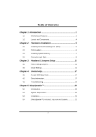
6 2.3 Installing System Memory 7 2.4 Connectors and Slots 9 Chapter 3: Headers & Jumpers Setup 11 3.1 How to Setup Jumpers 11 3.2 Detail Settings 11 Chapter 4: Useful Help 17 4.1 Award BIOS Beep Code 17 4.2 Extra Information 17 4.3 Troubleshooting 19 Chapter 5: WarpSpeeder - Biostar GEFORCE 6100-M9 | GeForce 6100-M9 user's manual - Page 3
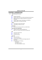
GeForce 6100-M9 CHAPTER 1: INTRODUCTION 1.1 MOTHERBOARD FEATURES CPU Supports Socket 939. Supports AMD Athlon 64 FX/ Athlon 64/ Athlon 64 X2 processor. AMD 64 architecture enables simultaneous 32 and 64 bit computing. Supports HyperTransport Technology up to 2000MT/s. Supports AMD Cool'n'Quiet - Biostar GEFORCE 6100-M9 | GeForce 6100-M9 user's manual - Page 4
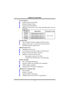
GeForce 6100-M9 System Memory Supports Dual Channel DDR.. Supports 8 banks in total. Supports DDR-266/333/400. Maximum memory size is up to 4GB. (Following table is only for reference.) DIMM Socket Location DDR Module Total Memory Size DIMMA1 128MB/256MB/512MB/1GB *1 DIMMA2 DIMMB1 128MB/ - Biostar GEFORCE 6100-M9 | GeForce 6100-M9 user's manual - Page 5
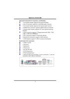
GeForce 6100-M9 Internal On-board I/O Connectors and Headers 1 front panel header supports front panel facilities. 1 CD-in connector supports 1 CD-ROM audio-in device. 1 front audio header supports front panel audio function. 1 S/PDIF-Out connector supports digital audio-out function. 1 chassis - Biostar GEFORCE 6100-M9 | GeForce 6100-M9 user's manual - Page 6
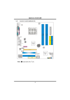
GeForce 6100-M9 1.2 LAYOUT AND COMPONENTS JKBMS1 JKBV1 JCFAN1 CPU1 JATXPWR1 JCOM1 JPRNT1 DIMM B1 DIMMB2 DIMM A1 DIMMA2 JVGA1 JUSB1 JUSBV1 JATXPWR2 JUSBLAN1 JAUDIO1 JAUDIO2 LAN PHY PCI-EX1_1 JCDIN1 Codec JSPDIF_OUT1 GeForce 6100 BAT1 PC I- EX 1 6 PCI1 JUSBV2 JUSB2 JUSB3 Super - Biostar GEFORCE 6100-M9 | GeForce 6100-M9 user's manual - Page 7
GeForce 6100-M9 CHAPTER 2: HARDWARE INSTALLATION 2.1 INSTALLING CENTRAL PROCESSING UNIT (CPU) Step 1: Remove the socket protection cap. Step 2: Pull the lever toward direction A from the socket and then raise the lever up to a 90-degree angle. 90 A Step 3: Look for the white triangle on socket, and - Biostar GEFORCE 6100-M9 | GeForce 6100-M9 user's manual - Page 8
GeForce 6100-M9 Step 4: Hold the CPU down firmly, and then close the lever toward direct B to complete the installation. B Step 5: Put the CPU Fan on the CPU and buckle it. Connect the CPU FAN power cable to the JCFAN1. This completes the installation. 2.2 FAN HEADERS These fan headers support - Biostar GEFORCE 6100-M9 | GeForce 6100-M9 user's manual - Page 9
DIMMB1 DIMMB2 DIMMA1 DIMMA 2 GeForce 6100-M9 2.3 INSTALLING SYSTEM MEMORY 2.2.1 DDR Module installation 1. Unlock a DIMM slot by pressing the retaining clips outward. Align a DIMM on the slot such that the notch on the DIMM matches - Biostar GEFORCE 6100-M9 | GeForce 6100-M9 user's manual - Page 10
GeForce 6100-M9 2.2.2 DDR Installation Notice For AMD K8 939 CPU launched before Rev. E, please follow the table below to install your DDR memory module, or the system may not boot up or may not function properly. (Please refer to Table 1 for CPU Revision) "SS" represents Single Side DDR memory - Biostar GEFORCE 6100-M9 | GeForce 6100-M9 user's manual - Page 11
GeForce 6100-M9 2.4 CONNECTORS AND SLOTS FDD1: Floppy Disk Connector The motherboard provides a standard floppy disk connector that supports 360K, 720K, 1.2M, 1.44M and 2.88M floppy disk types. This connector supports the provided floppy drive ribbon cables. 33 1 34 2 IDE1/IDE2: Hard Disk - Biostar GEFORCE 6100-M9 | GeForce 6100-M9 user's manual - Page 12
GeForce 6100-M9 PCI1~PCI2: Peripheral Component Interconnect Slots This motherboard is equipped with 2 standard PCI slots. PCI stands for Peripheral Component Interconnect, and it is a bus standard for expansion cards. This PCI slot is designated - Biostar GEFORCE 6100-M9 | GeForce 6100-M9 user's manual - Page 13
GeForce 6100-M9 CHAPTER 3: HEADERS & JUMPERS SETUP 3.1 HOW TO SETUP JUMPERS The panel (JUSB2/JUSB3) are powered by +5V standby voltage. JUSBV1 1 3 1 3 1 3 Pin 1-2 close (Default) JUSBV2 1 3 1 3 31 Pin 2-3 close Note: In order to support this function "Power-On system via USB device - Biostar GEFORCE 6100-M9 | GeForce 6100-M9 user's manual - Page 14
GeForce 6100-M9 JKBV1: Power Source Header for PS/2 Keyboard and Mouse 13 1 3 Pin 1-2 Close +5V for PS/2 keyboard and mouse. 1 3 Pin 2-3 close PS/2 keyboard and mouse are powered by +5V standby voltage. Note: In order to support this function "Power-on system via keyboard and mouse", "JKBV1 - Biostar GEFORCE 6100-M9 | GeForce 6100-M9 user's manual - Page 15
GeForce 6100-M9 JATXPWR2: ATX Power Source Connector By connecting this connector, it will provide +12V to CPU power circuit. Pin Assignment 4 Serial ATA Connectors The motherboard has a PCI to SATA Controller with 2 channels SATA interface, it satisfies the SATA 2.0 spec and with transfer rate - Biostar GEFORCE 6100-M9 | GeForce 6100-M9 user's manual - Page 16
GeForce 6100-M9 JPANEL1: Front Panel Header This 24-pin connector includes Power-on, Reset, HDD LED, Power LED, Sleep button, speaker Sleep button N/A Power LED Power-on button IrDA Connector JCDIN1: CD-ROM Audio-in Connector This connector allows user to connect the audio source from the - Biostar GEFORCE 6100-M9 | GeForce 6100-M9 user's manual - Page 17
GeForce 6100-M9 JAUDIO2: Front Panel Audio Header This header allows user to connect the front audio output cable with the PC front panel. It will disable the output on back panel audio connectors. Pin Assignment 1 Mic-in/Stereo MIC-in R 2 Ground 3 Stereo MIC-in L 4 Audio power 5 Right - Biostar GEFORCE 6100-M9 | GeForce 6100-M9 user's manual - Page 18
GeForce 6100-M9 JSPDIF_OUT1: Digital Audio-out Connector This connector allows user to connect the PCI bracket SPDIF output header. 1 3 Pin Assignment 1 +5V 2 SPDIF_OUT 3 Ground JCMOS1: Clear CMOS Header By placing the jumper on pin2-3, it allows user to restore the BIOS safe setting and - Biostar GEFORCE 6100-M9 | GeForce 6100-M9 user's manual - Page 19
GeForce 6100-M9 CHAPTER 4: USEFUL HELP 4.1 AWARD BIOS BEEP CODE Beep Sound One long beep followed by two short beeps High-low siren sound One Short beep when system boot-up Long beeps every other second Meaning Video card not found or video card memory bad CPU overheated System will shut down - Biostar GEFORCE 6100-M9 | GeForce 6100-M9 user's manual - Page 20
GeForce 6100-M9 B. CPU Overheated If the system shutdown automatically after power on system for seconds, that means the CPU protection function has been activated. When the CPU is over heated, the motherboard will shutdown automatically to avoid a damage of the CPU, and the system may not power on - Biostar GEFORCE 6100-M9 | GeForce 6100-M9 user's manual - Page 21
GeForce 6100-M9 4.3 TROUBLESHOOTING Problem Solution 1. No power to the system at all 1. Make sure power cable is Power light don't illuminate, fan securely plugged in. inside power supply does not turn 2. Replace cable. on. 3. Contact technical support Failure." Review system's equipment - Biostar GEFORCE 6100-M9 | GeForce 6100-M9 user's manual - Page 22
GeForce 6100-M9 CHAPTER 5: WARPSPEEDER™ 5.1 INTRODUCTION [WarpSpeeder™], a new powerful control utility, features three user-friendly functions including Overclock Manager, Overvoltage Manager, and Hardware Monitor. With the Overclock Manager, users can easily adjust the frequency they prefer or - Biostar GEFORCE 6100-M9 | GeForce 6100-M9 user's manual - Page 23
GeForce 6100-M9 5.3 INSTALLATION 1. Execute the setup execution file, and then the following dialog will pop up. Please click "Next" button " button. Usage: The following figures are just only for reference, the screen printed in this user manual will change according to your motherboard on hand. 21 - Biostar GEFORCE 6100-M9 | GeForce 6100-M9 user's manual - Page 24
GeForce 6100-M9 5.4 [WARPSPEEDER™] INCLUDES 1 TRAY ICON AND 5 PANELS 1. Tray Icon: Whenever the Tray Icon utility is launched, it will display a little tray icon on the right side of Windows Taskbar. This utility is responsible for conveniently invoking [WarpSpeeder™] Utility. You can use the mouse - Biostar GEFORCE 6100-M9 | GeForce 6100-M9 user's manual - Page 25
GeForce 6100-M9 2. Main Panel If you click the tray icon, [WarpSpeeder™] utility will be invoked. Please refer to the following figure; the utility's first window you will see is Main Panel. Main Panel contains features as follows: a. Display the CPU Speed, CPU external clock, Memory clock, AGP - Biostar GEFORCE 6100-M9 | GeForce 6100-M9 user's manual - Page 26
GeForce 6100-M9 3. Voltage Panel Click the Voltage button in Main Panel, the button will be highlighted and the Voltage Panel will slide out to up as the following figure. In this panel, you can decide to increase CPU core voltage and Memory voltage or not. The default setting is "No". If you want - Biostar GEFORCE 6100-M9 | GeForce 6100-M9 user's manual - Page 27
GeForce 6100-M9 4. Overclock Panel Click the Overclock button in Main Panel, the button will be highlighted and the Overclock Panel will slide out to left as the following figure. Overclock Panel contains the these features: a. "-3MHz button", "-1MHz button", "+1MHz button", and "+3MHz button": - Biostar GEFORCE 6100-M9 | GeForce 6100-M9 user's manual - Page 28
GeForce 6100-M9 c. "Auto-overclock button": User can click this button and [WarpSpeeder™] will set the to the Recovery Dialog's setting. Note: Because the testing programs, invoked in Auto-overclock and Verify, include DirectDraw, Direct3D and DirectShow tests, the DirectX 8.1 or newer runtime - Biostar GEFORCE 6100-M9 | GeForce 6100-M9 user's manual - Page 29
GeForce 6100-M9 6. About Panel Click the "about" button in Main Panel, the button will be highlighted and the About Panel will slide out to up as the following figure. In this panel, you can get model name and detail information in hints of all the chipset that are related to overclocking. You can - Biostar GEFORCE 6100-M9 | GeForce 6100-M9 user's manual - Page 30
GeForce 6100-M9 Note: Because the overclock, overvoltage, and hardware monitor features are controlled by several separate chipset, [WarpSpeeder™] divide these features to separate panels. If one chipset is not on board,
-
 1
1 -
 2
2 -
 3
3 -
 4
4 -
 5
5 -
 6
6 -
 7
7 -
8
-
9
-
10
-
11
-
12
-
13
-
14
-
15
-
16
-
17
-
18
-
19
-
20
-
21
-
22
-
23
-
24
-
25
-
26
-
27
-
28
-
29
-
30
 |
 |

GeForce 6100-M9
i
FCC Information and Copyright
This equipment has been tested and found to comply with the limits of a Class
B digital device, pursuant to Part 15 of the FCC Rules. These limits are designed
to provide reasonable protection against harmful interference in a residential
installation. This equipment generates, uses and can radiate radio frequency
energy and, if not installed and used in accordance with the instructions, may
cause harmful interference to radio communications. There is no guarantee
that interference will not occur in a particular installation.
The vendor makes no representations or warranties with respect to the
contents here and specially disclaims any implied warranties of merchantability
or fitness for any purpose. Further the vendor reserves the right to revise this
publication and to make changes to the contents here without obligation to
notify any party beforehand.
Duplication of this publication, in part or in whole, is not allowed without first
obtaining the vendor’s approval in writing.
The content of this user’s manual is subject to be changed without notice and
we will not be responsible for any mistakes found in this user’s manual. All the
brand and product names are trademarks of their respective companies.