Biostar GEFORCE 6100-M9 GeForce 6100-M9 user's manual - Page 18
JSPDIF_OUT1: Digital Audio-out Connector, JCMOS1: Clear CMOS Header, Clear CMOS Procedures - m9 bios
 |
View all Biostar GEFORCE 6100-M9 manuals
Add to My Manuals
Save this manual to your list of manuals |
Page 18 highlights
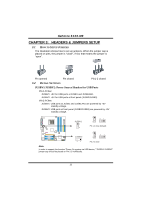
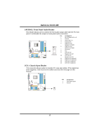
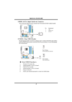
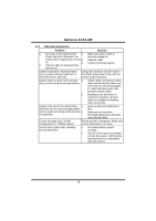
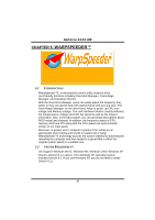
GeForce 6100-M9 JSPDIF_OUT1: Digital Audio-out Connector This connector allows user to connect the PCI bracket SPDIF output header. 1 3 Pin Assignment 1 +5V 2 SPDIF_OUT 3 Ground JCMOS1: Clear CMOS Header By placing the jumper on pin2-3, it allows user to restore the BIOS safe setting and the CMOS data, please carefully follow the procedures to avoid damaging the motherboard. 1 3 Pin 1-2 Close: Normal Operation (Default). 1 13 3 Pin 2-3 Close: Clear CMOS data. ※ Clear CMOS Procedures: 1. Remove AC power line. 2. Set the jumper to "Pin 2-3 close". 3. Wait for five seconds. 4. Set the jumper to "Pin 1-2 close". 5. Power on the AC. 6. Reset your desired password or clear the CMOS data. 16
-
 1
1 -
2
-
3
-
4
-
5
-
6
-
7
-
8
-
9
-
10
-
11
-
12
-
 13
13 -
 14
14 -
 15
15 -
 16
16 -
 17
17 -
 18
18 -
 19
19 -
 20
20 -
 21
21 -
 22
22 -
 23
23 -
24
-
25
-
26
-
27
-
28
-
29
-
30
 |
 |
GeForce 6100-M9
16
JSPDIF_OUT1: Digital Audio-out Connector
This connector allows user to connect the PCI bracket SPDIF output header.
Pin
Assignment
1
+5V
2
SPDIF_OUT
1
3
3
Ground
JCMOS1: Clear CMOS Header
By placing the jumper on pin2-3, it allows user to restore the BIOS safe setting
and the CMOS data, please carefully follow the procedures to avoid damaging
the motherboard.
1
3
Pin 1-2 Close:
Normal Operation (Default).
1
3
1
3
Pin 2-3 Close:
Clear CMOS data.
※
Clear CMOS Procedures:
1.
Remove AC power line.
2.
Set the jumper to “Pin 2-3 close”.
3.
Wait for five seconds.
4.
Set the jumper to “Pin 1-2 close”.
5.
Power on the AC.
6.
Reset your desired password or clear the CMOS data.