Biostar K8M800 Setup Manual - Page 14
JUSB1/JUSB2/JUSB3: Headers for USB 2.0 Ports at Front Panel, JUSB3 is optional, JUSBV1/JUSBV2: Power
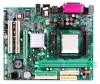 |
View all Biostar K8M800 manuals
Add to My Manuals
Save this manual to your list of manuals |
Page 14 highlights
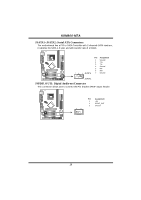
K8M800-M7A JUSB1/JUSB2/JUSB3: He ade rs for USB 2.0 Ports at Front Panel (JUSB3 is optional) This header allows user to connect additional USB cable on the PC f ront panel, and also can be connected with internal USB devices, like USB card reader. Pin Assignment 1 +5V (fused) 2 +5V (fused) 3 USB- 4 USB- 5 USB+ 6 USB+ 7 Ground JUSB1 JUSB2 JUSB3 8 Ground 2 10 9 Key 10 NC 1 9 JUSBV1/JUSBV2: Powe r Source Heade rs for USB Ports Pin 1-2 Close: JUSBV1: +5V for USB ports at JUSBLAN1. JUSBV2: +5V for USB ports at f ront panel (JUSB1/JUSB2/JUSB3). Pin 2-3 Close: JUSBV1: USB ports at JUSBLAN1 are powered by +5V standby voltage. JUSBV2: USB ports at front panel (JUSB1/JUSB2/JUSB3) are powered by +5V standby voltage. JUS BV1 13 3 1 3 1 Pin 1-2 close JUSBV 2 3 1 3 1 3 1 Pin 2-3 close Note: In order to s upport this function "Power-On s ystem vi a USB devic e," "JUSBV1/ JUSBV2" jumper cap should be plac ed on Pin 2-3 indi viduall y. 12
-
 1
1 -
2
-
3
-
4
-
5
-
6
-
7
-
8
-
 9
9 -
 10
10 -
 11
11 -
 12
12 -
 13
13 -
 14
14 -
 15
15 -
 16
16 -
 17
17 -
 18
18 -
 19
19 -
20
-
21
-
22
-
23
-
24
-
25
-
26
-
27
-
28
-
29
-
30
-
31
-
32
-
33
-
34
-
35
-
36
-
37
-
38
-
39
-
40
-
41
-
42
-
43
-
44
-
45
-
46
-
47
-
48
-
49
-
50
-
51
-
52
-
53
-
54
-
55
-
56
-
57
-
58
-
59
-
60
-
61
-
62
-
63
-
64
-
65
-
66
-
67
-
68
-
69
-
70
-
71
 |
 |
