Biostar K8NHA-M K8NHA M user's manual
Biostar K8NHA-M Manual
 |
View all Biostar K8NHA-M manuals
Add to My Manuals
Save this manual to your list of manuals |
Biostar K8NHA-M manual content summary:
- Biostar K8NHA-M | K8NHA M user's manual - Page 1
BIOSTAR Motherboard FCC Statement This equipment has been tested and found to comply with the and radiate radio frequency energy and, if not installed and used in accordance with the instructions, may cause harmful interference to radio communications. However, there is no guarantee that interference - Biostar K8NHA-M | K8NHA M user's manual - Page 2
BIOSTAR Motherboard affiliated companies. Copyright Notice No part of this manual may be reproduced or transmitted in any form or herein may be trademarks and/ or service marks of their respective owners. Intel of Silicon Integrated Systems Corporation. PS/2 is registered trademark of International - Biostar K8NHA-M | K8NHA M user's manual - Page 3
BIOSTAR Motherboard Important Safety Information 1. Please read these safety instructions carefully. 2. Please keep this User's Manual for later 15. If one of the following situations arises, get the equipment checked by service personnel: a. The Power cord or plug is damaged. b. Liquid has - Biostar K8NHA-M | K8NHA M user's manual - Page 4
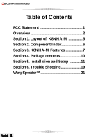
BIOSTAR Motherboard Table of Contents FCC Statement 1 Overview 2 Section 1. Layout of K8NHA-M 5 Section 2. Component Index 6 Section 3. K8NHA-M Features 7 Section 4. Package contents 10 Section 5. Installation and Setup 11 Section 6. Trouble Shooting 19 WarpSpeeder 21 TM English 4 - Biostar K8NHA-M | K8NHA M user's manual - Page 5
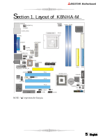
BIOSTAR Motherboard Section 1. Layout of K8NHA-M JKBMS1 1 JKBMSV1 1 JUSBV1 J1394_USB1 JCOM1 JCFAN1 1 DDR1 Socket 754 CPU1 Super I/O IT 8712F FDD1 1 JCOM3 JCOM2 JATXPWR2 JUSBLAN1 J1394A1 JSFAN2 1J U S B V 2 JAUDIO 1 JSPDIF_OUT 1 BIOS RTL8201BL 1 1 JAUDIO1 1 JSPDIF_IN 1 JCDIN2 - Biostar K8NHA-M | K8NHA M user's manual - Page 6
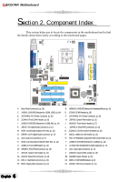
BIOSTAR Motherboard Section 2. Component Index This section helps you to locate the components in the motherboard and to find the details about them easily Selection for JUSBLAN1 (p. 14) J JAUDIO1: Front Audio Header (p. 17) K JSPDIF_IN: Digital Audio Connector (p. 17) L JSATA2-3: Serial ATA - Biostar K8NHA-M | K8NHA M user's manual - Page 7
BIOSTAR Motherboard Section 3. K8NHA-M Features In this section, you shall find all the information about the motherboard in your computer, including its features, layout, component index, various jumpers, headers, connectors, and also the installation guide to help you a quick and correct - Biostar K8NHA-M | K8NHA M user's manual - Page 8
BIOSTAR Motherboard Main Memory * Supports up to two DDR devices. * Supports 200/266/333/400MHz (with ECC) DDR devices. * Maximum memory size is 2GB. Total Memory Size with Unbuffered DIMMs DIMM Socket Location DDR Module Total Memory Size (MB) DDR1 DDR2 64MB/128MB/256MB/512MB/1GB*1 64MB/ - Biostar K8NHA-M | K8NHA M user's manual - Page 9
(optional). - 1 x IEEE 1394 port (optional) B. BIOS & Software BIOS * Award legal BIOS. * Supports APM1.2. * Supports ACPI. * Supports USB Function. * The setup procedures can be found in the Setup Driver CD. Software * Supports WarpspeederTM, 9th TouchTM, FLASHERTM, WatchdogTM, WinFlasherTM and - Biostar K8NHA-M | K8NHA M user's manual - Page 10
BIOSTAR Motherboard Section 4. Package contents Check what you have bought before you start your DIY action. If there are anything missing, please contact your dealer immediately. * HDD Cable X 1 * FDD Cable X 1 * User's Manual X1 * USB 2.0 Cable X1 (optional) * Rear I/O Panel for ATX Case X1 ( - Biostar K8NHA-M | K8NHA M user's manual - Page 11
BIOSTAR Motherboard Section 5. Installation and Setup In this section, you will learn how to install the CPU, DDR Module, and also how to set up jumpers and all the information about the components on the motherboard on the motherboard. 1. CPU Installation The motherboard supports the AMD Athlon - Biostar K8NHA-M | K8NHA M user's manual - Page 12
BIOSTAR Motherboard (2) System Fan Headers: JSFAN1/JSFAN2 Pin Assignment 1 Ground 2 +12V 3 FAN RPM Jumpers, Headers, Connectors & Slots: (1) Floppy Disk Connector: FDD1 The motherboard provides a standard floppy disk connector that supports 360K, 720K, 1.2M, 1.44M and 2.88M floppy disk types. - Biostar K8NHA-M | K8NHA M user's manual - Page 13
BIOSTAR Motherboard (2) Hard Disk Connectors: IDE1/ IDE2 The motherboard supports modem only. (6) Serial ATA Connector: (JSATA1/JSATA2/JSATA3: optional) The motherboard has a PCI to SATA Controller with 2 channels STAT interface. It satisfies the SATA 1.0 spec clear the CMOS memory of date, time - Biostar K8NHA-M | K8NHA M user's manual - Page 14
BIOSTAR Motherboard (8) Wake On LAN Header: JWOL1 (optional) This connector allows you to +5V_SB 2 Ground 3 Wake up 1 JWOL1 (9) Front USB Header: JUSB1/ (JUSB2: optional) The motherboard provides one/(two) USB 2.0 Pin Header. USB 2.0 technology increases Data transfer rate up to a maximum - Biostar K8NHA-M | K8NHA M user's manual - Page 15
BIOSTAR Motherboard (12) CD-ROM Audio-In Header: JCDIN1/JCDIN2 This header allows you to receive stereo audio input from sound sources, such as CD-ROM, TV Tuner, MPEG card, etc. Pin Assignment 1 Left Channel Input 2 Ground 3 Ground 4 Right Channel Input 1 JCDIN1/JCDIN2 ( - Biostar K8NHA-M | K8NHA M user's manual - Page 16
mouse 1 Pin 2-3 close +5V_SB 5V standby for keyboard and 1 mouse to power on your system (16) Power Connectors: JATXPWER1/ JATXPWR2 The motherboard supports ATX power supply for the power system. Before installing the power supply connector, please make sure that all components are installed - Biostar K8NHA-M | K8NHA M user's manual - Page 17
BIOSTAR Motherboard (18) Digital Audio Connector: JSPDIF_OUT/ (JSPDIF_IN: optional) The connector is used to connect SPDIF (Sony & Philips Digital Interconnect Format) interface for digital audio transmission. Pin Assignment 1 +5V 1 2 SPDIF_OUT 3 Ground (19) Front Panel Audio Header: JAUDIO1 - Biostar K8NHA-M | K8NHA M user's manual - Page 18
BIOSTAR Motherboard (22) COM3 Header: JCOM3 (optional) Pin Assignment Pin Assignment 1 RIN1 2 RIN3 3 DOUT2 4 ROUT3 9 1 5 Ground 7 DOUT1 6 RIN2 8 RIN4 10 2 9 -XRI1 10 NA (23) Back Panel Connectors 6 Channel Speakers Speaker Out Line In/ Rear Speaker Mic In/ Center & Bass English 18 - Biostar K8NHA-M | K8NHA M user's manual - Page 19
BIOSTAR Motherboard Section 6. Trouble Shooting PROBABLE SOLUTION No power to the system at all; power light * Make sure power cable is securely doesn't illuminate; fan inside power supply plugged in.* Replace cable. does not turn on. Indicator light on keyboard * Contact technical support Review - Biostar K8NHA-M | K8NHA M user's manual - Page 20
BIOSTAR Motherboard PROBABLE SOLUTION Scree is blank. Screen goes blank periodically. * Check the power connectors to monitor and to system. Make sure monitor is connected to display card. * Disable screen saver. Memory problem. * Reboot computer. Reinstall memory, and make sure that all - Biostar K8NHA-M | K8NHA M user's manual - Page 21
BIOSTAR Motherboard chipset information. Also, in the About panel, you can get detail descriptions about BIOS model and chipsets. In addition, the frequency status of CPU, memory original system speed or a suitable one. System Requirement OS Support: Windows 98 SE, Windows Me, Windows 2000, Windows - Biostar K8NHA-M | K8NHA M user's manual - Page 22
BIOSTAR Motherboard 2. When you see the following dialog in setup procedure, it means setup is completed. If the "Launch the WarpSpeeder Tray Utility" checkbox is checked, the - Biostar K8NHA-M | K8NHA M user's manual - Page 23
BIOSTAR Motherboard Usage The following figures are just only for reference, the screen printed in this user manual will change according to your motherboard on features as follows: a. Display the CPU Speed, CPU external clock, Memory clock, AGP clock, and PCI clock information. b. Contains About, - Biostar K8NHA-M | K8NHA M user's manual - Page 24
BIOSTAR Motherboard c. With a user-friendly Status Animation, it can represent 3 overclock percentage stages: Duck as the following figure. In this panel, you can decide to increase CPU core voltage and Memory voltage or not. The default setting is "No". If you want to get the best performance - Biostar K8NHA-M | K8NHA M user's manual - Page 25
BIOSTAR Motherboard 4. Overclock Panel Click the Overclock button in Main Panel, the button will be highlighted and the Overclock Panel will slide out to left as the following figure. Overclock Panel contains these features: 25 English - Biostar K8NHA-M | K8NHA M user's manual - Page 26
BIOSTAR Motherboard a. "-3MHz button", "-1MHz button", "+1MHz button", and "+3MHz button": provide user the ability to do real-time overclock adjustment. Warning: Manually overclock is potentially dangerous, especially when the overclocking percentage is over 110 %. We strongly recommend you verify - Biostar K8NHA-M | K8NHA M user's manual - Page 27
BIOSTAR Motherboard 5. Hardware Monitor Panel Click the Hardware Monitor button in Main get model name and detail information in hints of all the chipset that are related to overclocking. You can also get the mainboard's BIOS model and the Version number of [ WarpSpeederTM ] utility. 27 English - Biostar K8NHA-M | K8NHA M user's manual - Page 28
BIOSTAR Motherboard Note: Because the overclock, overvoltage, and hardware monitor features are controlled by several separate chipset, [ WarpSpeederTM ] divide these features to separate panels. If one chipset is not on board, the correlative button in Main panel will be disabled, but will not
-
 1
1 -
 2
2 -
 3
3 -
 4
4 -
 5
5 -
 6
6 -
 7
7 -
8
-
9
-
10
-
11
-
12
-
13
-
14
-
15
-
16
-
17
-
18
-
19
-
20
-
21
-
22
-
23
-
24
-
25
-
26
-
27
-
28
 |
 |
1
English
English
English
English
English
BIOSTAR
Motherboard
FCC Statement
This equipment has been tested and found to comply with the limits for a Class
B digital device, pursuant to Part 15 of the FCC rules.
These limits are designed to
provide reasonable protection against harmful interference in a residential installation.
Any changes or modification made to this equipment void the user’s authority
to operate this equipment.
This equipment generates, uses, and radiate radio frequency energy and, if not
installed and used in accordance with the instructions, may cause harmful interference
to radio communications.
However, there is no guarantee that interference will not
occur in a particular installation.
If this equipment does cause harmful interference to
radio or television reception, which can be determined by turning the equipment off and
on, the user is encouraged to try to correct the interference by one or more of the
following measures:
* Reorient or relocate the receiving antenna.
* Increase the separation between the equipment and receiver.
* Connect the equipment into an outlet on a circuit different from that to which
the receiver is connected.
* Consult the dealer or an experienced radio/TV technician for help.
* All external cables connecting to this basic unit must be shielded.
C. D. C. Statement
This digital apparatus does not exceed the Class B limits for radio noise emissions
from digital apparatus as set out in the radio interference regulations or the Canadian
Department of Communications.
CE Mark
This equipment is in conformity with the EMC directive.