Biostar M5ATC M5ATC user's manual - Page 13
Assignment, Function
 |
View all Biostar M5ATC manuals
Add to My Manuals
Save this manual to your list of manuals |
Page 13 highlights
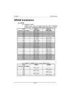
Chapter 1 System Board Pin Assignment Function Pin Assignment No. No. 1 Speaker 14 +5V 2 NC Speaker 15 Ground 3 Ground Connector 16 No Connection 4 +5V 17 Green Control 5 Power LED(+) 18 Ground 6 No Connection Power LED 19 No Connection 7 Ground & 20 HDD LED(-) 8 Key lock Keylock 21 HDD LED(+) 9 Ground 22 +5V 10 Power Switch ATX Power 23 No Connection 11 Standby Voltage Button 24 IRRX 12 Reset Control Reset 25 Ground 13 Ground 26 IRTX Function VCC Ground NC Green Switch NC HDD LED IrDA Connector
-
 1
1 -
2
-
3
-
4
-
5
-
6
-
7
-
 8
8 -
 9
9 -
 10
10 -
 11
11 -
 12
12 -
 13
13 -
 14
14 -
 15
15 -
 16
16 -
 17
17 -
 18
18 -
19
-
20
-
21
-
22
-
23
-
24
-
25
-
26
-
27
-
28
-
29
-
30
-
31
-
32
-
33
-
34
-
35
-
36
-
37
-
38
-
39
-
40
-
41
-
42
-
43
-
44
-
45
-
46
-
47
-
48
-
49
-
50
 |
 |

Chapter 1
System Board
±·²³´
ǵ²²»¸³µ´½
(Ë)· · · · *:+
´ ´ ´ >AÇ0.Ê´ ´ ´ ´ ´ ´ >¸³³»´ ´
³³
=ÊÊ
´ ´ ´ F!C´ ´ ´ ´ ´ ´ ´ ´
³
.É
±±
Ä-´
³
.É´(ËÊ´ ´ ´ ´ ´ ´ øÊÅ
´ ´ ´ ´ ´ %3
´´´´´´%
´ ´ ´ ´ ÄÈËÅ#ËA´ ´ ´ ´ ȶ'³¸´(ËÊ´ ´ ´ ű1´ ´ AËÄ˱
´ ´ ´ ´ ´ ´ ´ ´ ´ ´ ´ ´ ´ ´ ´ ´ ´ ´ ´ ´ ´ B´ ´ ´ ´ ´ ´ ´ ȶ'³¸
´ ´ ´ ´ ´ ´ ´ ´ ´ ´ ´ ´ ´ ´ ´ ´ ´ ´ ´ #³ÀͶ¼,´ ´ ´
±
$ξ¾¶»
Pin
Assignment
Function
Pin
Assignment
Function
No.
No.
1
Speaker
14
+5V
VCC
2
NC
Speaker
15
Ground
Ground
3
Ground
Connector
16
No Connection
NC
4
+5V
17
Green Control
Green
5
Power LED(+)
18
Ground
Switch
6
No Connection
Power LED
19
No Connection
NC
7
Ground
&
20
HDD LED(-)
HDD
8
Key lock
Keylock
21
HDD LED(+)
LED
9
Ground
22
+5V
10
Power Switch
ATX Power
23
No Connection
IrDA
11
Standby Voltage
Button
24
IRRX
Connector
12
Reset Control
Reset
25
Ground
13
Ground
26
IRTX