Biostar M6VCG M6VCG user's manual - Page 38
CD Audio-In Connectors : J7/J8, 9.2 Telephony Connector : J9, 9.3 AUX Audio in Connector :
 |
View all Biostar M6VCG manuals
Add to My Manuals
Save this manual to your list of manuals |
Page 38 highlights
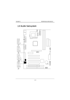
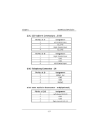
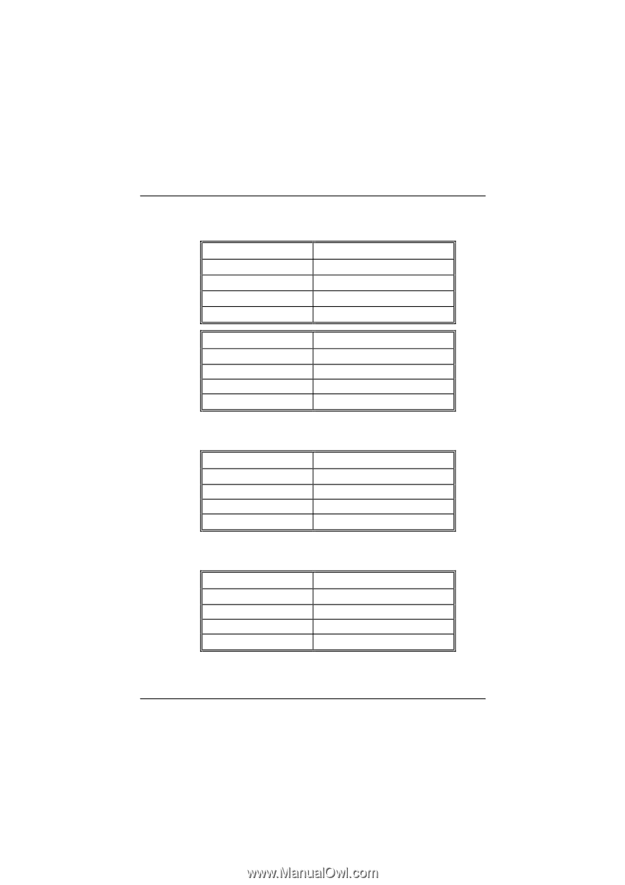
Chapter 1 Motherboard Description 1.9.1 CD Audio-In Connectors : J7/J8 Pin No. of J7 1 2 3 4 Assignment Left Channel Input CD_GND Right Channel Input CD_GND Pin No. of J8 1 2 3 4 Assignment Right Channel Input GND GND Left Channel Input 1.9.2 Telephony Connector : J9 Pin No. of J9 1 2 3 4 Assignment MONO_Out GND GND PHONE 1.9.3 AUX Audio in Connector : J10(Optional) Pin No. of J10 1 2 3 4 Assignment Left channel AUX_IN GND GND Right channel AUX_IN
-
 1
1 -
2
-
3
-
4
-
5
-
6
-
7
-
8
-
9
-
10
-
11
-
12
-
13
-
14
-
15
-
16
-
17
-
18
-
19
-
20
-
21
-
22
-
23
-
24
-
25
-
26
-
27
-
28
-
29
-
30
-
31
-
32
-
 33
33 -
 34
34 -
 35
35 -
 36
36 -
 37
37 -
 38
38 -
 39
39 -
 40
40 -
 41
41 -
 42
42 -
 43
43 -
44
-
45
-
46
-
47
-
48
-
49
-
50
-
51
-
52
-
53
-
54
-
55
-
56
-
57
-
58
-
59
-
60
-
61
-
62
-
63
-
64
-
65
-
66
-
67
-
68
-
69
-
70
-
71
-
72
-
73
-
74
-
75
-
76
-
77
-
78
-
79
-
80
-
81
-
82
-
83
-
84
-
85
 |
 |
Chapter 1
Motherboard Description
ı++
1.9.1 CD Audio-In Connectors : J7/J8
Pin No. of J7
Assignment
1
Left Channel Input
2
CD_GND
3
Right Channel Input
4
CD_GND
Pin No. of J8
Assignment
1
Right Channel Input
2
GND
3
GND
4
Left Channel Input
1.9.2 Telephony Connector : J9
Pin No. of J9
Assignment
1
MONO_Out
2
GND
3
GND
4
PHONE
1.9.3 AUX Audio in Connector : J10(Optional)
Pin No. of J10
Assignment
1
Left channel AUX_IN
2
GND
3
GND
4
Right channel AUX_IN