Biostar M7NCD ULTRA M7NCD Ultra BIOS setup guide - Page 17
Integrated Peripherals - motherboard
 |
View all Biostar M7NCD ULTRA manuals
Add to My Manuals
Save this manual to your list of manuals |
Page 17 highlights
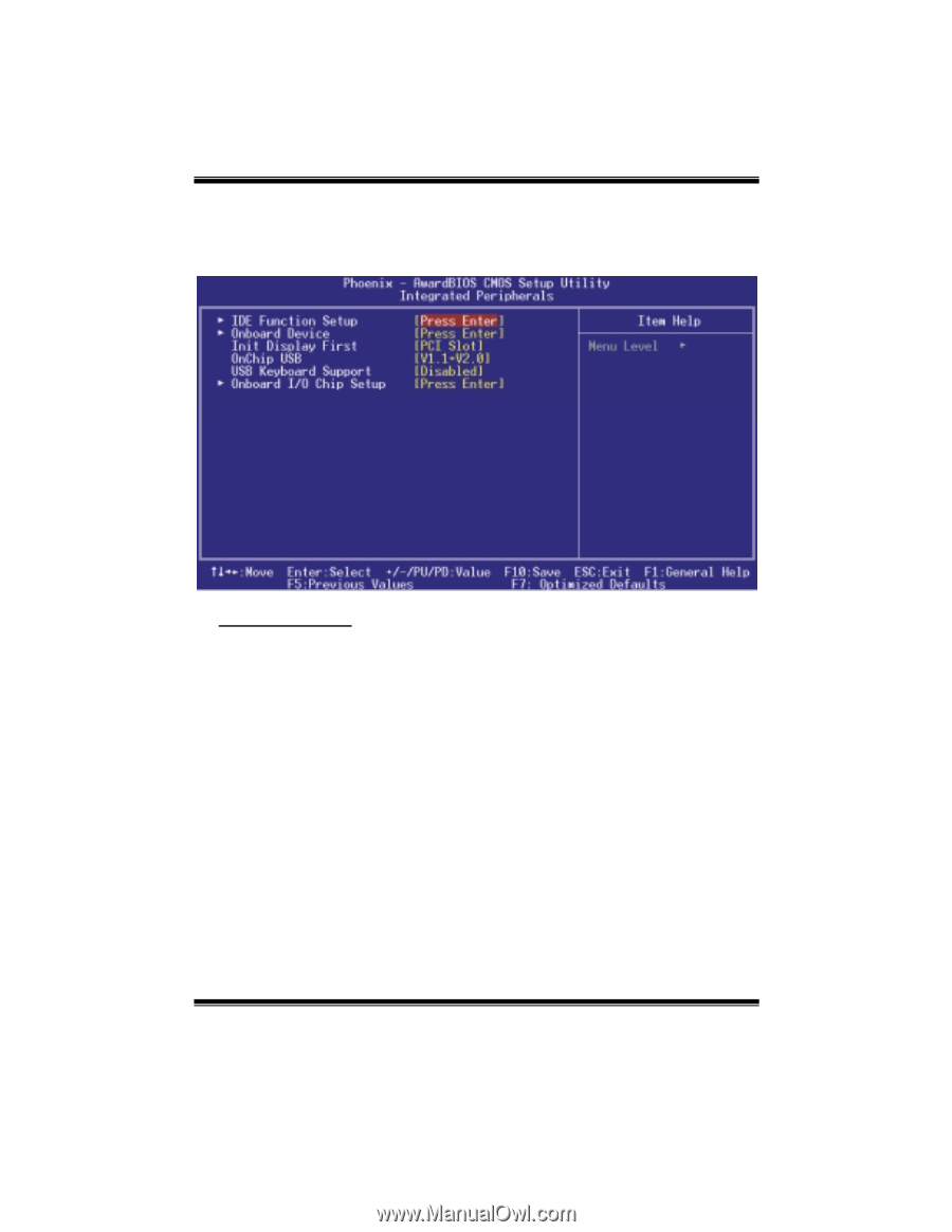
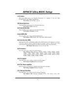
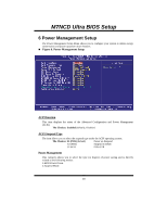
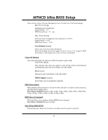
M7NCD Ultra BIOS Setup 5 Integrated Peripherals Figure 5. Integrated Peripherals IDE Function Setup The chipset contains a PCI IDE interface with support for two IDE channels. Select "Enabled" to activate the first and / or second IDE interface. If you install a primary and / or secondary add-in IDE interface, select "Disabled" to deactivate an interface. If you highlight the literal "Press Enter" next to the "Onchip IDE Control" label and then press the enter key, it will take you a submenu with the following options: OnChip IDE Channel 0/1 The motherboard chipset contains a PCI IDE interface with support for two IDE channels. Select "Enabled" to activate the first and/or second IDE interface. Select "Disabled" to deactivate an interface if you are going to install a primary and/or secondary add-in IDE interface. The Choices: Enabled (default), Disabled. Primary / Secondary Master / Slave PIO The IDE PIO (Programmed Input / Output) fields let you set a PIO mode (0-4) for each of the IDE devices that the onboard IDE interface supports. Modes 0 through 4 provides successively increased performance. In Auto mode, the system automatically determines the best mode for each device. The Choices: Auto (default), Mode0, Mode1, Mode2, Mode3, Mode4. 16
-
 1
1 -
2
-
3
-
4
-
5
-
6
-
7
-
8
-
9
-
10
-
11
-
 12
12 -
 13
13 -
 14
14 -
 15
15 -
 16
16 -
 17
17 -
 18
18 -
 19
19 -
 20
20 -
 21
21 -
 22
22 -
23
-
24
-
25
-
26
-
27
-
28
 |
 |