Biostar M7VKH M7VKH user's manual - Page 56
ECP Mode Use DMA
 |
View all Biostar M7VKH manuals
Add to My Manuals
Save this manual to your list of manuals |
Page 56 highlights
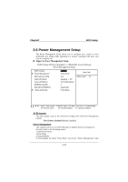
Chapter2 BIOS Setup Onboard FDD Controller Select Enabled if your system has a floppy disk controller (FDC) installed on the system board and if you wish to use it. If install and FDC or the system has no floppy drive, select Disabled in this field. The Choices: Enabled (default), Disabled. Onboard Serial Port 1 / 2 Select an address and corresponding interrupt for the serial port. The Choices: Disabled, Auto (default), 3F8/IRQ4, 2F8/IRQ3, 3E8/IRQ4, 2E8/IRQ3. UART 2 Mode This item allows you to determine which InfraRed (IR) function of the onboard I/O chip, you wish to use. The Choices: HPSIR, Standard (default), HPSIR ,ASKIR. IR Function Duplex This item allows you to determine which Infra Red (IR) function of onboard I/O chip. The Choices: Half (default), Full. TX, RX inverting enable This item allows you to determine the active of Rx, Tx. The Choices: No/No, No/Yes (default), Yes/No, Yes/Yes. Onboard Parallel Port This item allows you to determine access onboard parallel port controller with which I/O address. The Choices: Disable, 3BC/IRQ7, 378/IRQ7 (default), 278/IRQ5 Onboard Parallel Mode Select an operating mode for the onboard parallel (printer) port. Normal EPP (Enhanced Parallel Port) ECP (Extended Capabilities Port) ECP+EPP PC AT parallel port Bidirectional Port Fast, buffered port Fast, buffered, Bidirectional Port. Select Normal unless you are certain your hardware and software both support EPP or ECP mode. The Choices: Normal (default), EPP, ECP, ECP/EPP ECP Mode Use DMA Select a DMA channel for the parallel port for use during ECP mode. The Choices: 3 (default), 1. 2-20
-
 1
1 -
2
-
3
-
4
-
5
-
6
-
7
-
8
-
9
-
10
-
11
-
12
-
13
-
14
-
15
-
16
-
17
-
18
-
19
-
20
-
21
-
22
-
23
-
24
-
25
-
26
-
27
-
28
-
29
-
30
-
31
-
32
-
33
-
34
-
35
-
36
-
37
-
38
-
39
-
40
-
41
-
42
-
43
-
44
-
45
-
46
-
47
-
48
-
49
-
50
-
 51
51 -
 52
52 -
 53
53 -
 54
54 -
 55
55 -
 56
56 -
 57
57 -
 58
58 -
 59
59 -
 60
60 -
 61
61 -
62
-
63
-
64
-
65
-
66
-
67
-
68
-
69
-
70
-
71
-
72
-
73
-
74
-
75
-
76
-
77
-
78
-
79
-
80
 |
 |
