Biostar P4M80-M7A V7.X P4M80-M7A user's manual - Page 17
JATXPWR1/PATXPWR2: Power Connectors, JAUDIO1: Front Panel Audio Header
 |
View all Biostar P4M80-M7A V7.X manuals
Add to My Manuals
Save this manual to your list of manuals |
Page 17 highlights
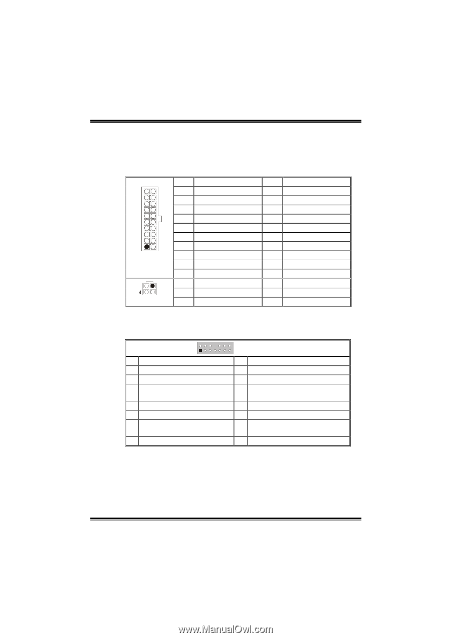
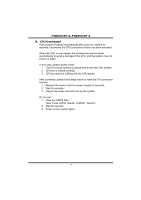
P4M800-M7 & P4M800-M7 A JATXPWR1/PATXPWR2: Power Connectors JATXPWR1: This connector allows user to connect with 20-pin power connector on the ATX power supply. JATXPWR2: By connecting this connector, it will provide +12V to CPU power circuit. 10 20 1 11 JATXPWR1 2 1 3 JATXPWR2 Pin Assignment 1 +3.3V 2 +3.3V 3 Ground 4 +5V 5 Ground 6 +5V 7 Ground 8 PW_ON 9 Standby Voltage +5V 10 +12V Pin Assignment 1 +12V 2 +12v Pin Assignment 11 +3.3V 12 -12V 13 Ground 14 PS_ON 15 Ground 16 Ground 17 Ground 18 -5V 19 +5V 20 +5V Pin Assignment 3 Ground 4 Ground JAUDIO1: Front Panel Audio Header This header allows user to connect the front audio out put cable with the PC front panel. It will disable the output on back panel audio connectors. 2 14 1 13 JAUDIO1 Pin Assignment Pin Assignment 1 Mic in/center 2 Ground 3 Mic power/Bass 4 Audio power 5 Right line out/Speaker out Right 6 Right line out/Speaker out Right 7 Reserved 8 Key 9 Left line out/Speaker out Left 10 Left line out/Speaker out Left 11 Right line in/Rear speaker Right 12 Right line in/Rear speaker Right 13 Left line in/Rear speaker Left 14 Left line in/Rear speaker Left 15
-
 1
1 -
2
-
3
-
4
-
5
-
6
-
7
-
8
-
9
-
10
-
11
-
 12
12 -
 13
13 -
 14
14 -
 15
15 -
 16
16 -
 17
17 -
 18
18 -
 19
19 -
 20
20 -
 21
21 -
 22
22 -
23
-
24
-
25
-
26
-
27
-
28
-
29
-
30
-
31
 |
 |