Biostar P4M890-M7 TE Bios Setup - Page 25
USB Device Setting
 |
View all Biostar P4M890-M7 TE manuals
Add to My Manuals
Save this manual to your list of manuals |
Page 25 highlights
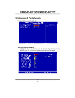
P4M900-M7 SE/P4M890-M7 TE Parallel Port Mode This item allows you to determine how the parallel port should function. The default value is SPP. The Choices: SPP (default) Using Parallel port as Standard Printer Port. EPP Using Parallel Port as Enhanced Parallel Port. ECP Using Parallel port as Extended Capabilities Port. ECP+EPP Using Parallel port as ECP & EPP mode. ECP Mode Use DMA Select a DMA Channel for the port. The Choices: 3 (default), 1. USB Device Setting Press Enter to configure the USB Device. USB 1.0/2.0 Controller These options allow you to enable or disable the USB 1.0/2.0 controller function. The Choices: Enabled (default), Disabled. 24
-
 1
1 -
2
-
3
-
4
-
5
-
6
-
7
-
8
-
9
-
10
-
11
-
12
-
13
-
14
-
15
-
16
-
17
-
18
-
19
-
 20
20 -
 21
21 -
 22
22 -
 23
23 -
 24
24 -
 25
25 -
 26
26 -
 27
27 -
 28
28 -
 29
29 -
 30
30 -
31
-
32
-
33
-
34
-
35
-
36
-
37
-
38
-
39
-
40
 |
 |

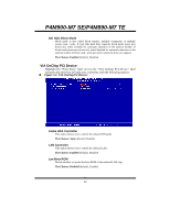
P4M900-M7 SE/P4M890-M7 TE
24
Parallel Port Mode
This item allows you to determine how the parallel port should function. The
default value is SPP.
The Choices:
SPP
(default)
Using Parallel port as Standard Printer Port.
EPP
Using Parallel Port as Enhanced Parallel Port.
ECP
Using Parallel port as Extended Capabilities Port.
ECP+EPP
Using Parallel port as ECP & EPP mode.
ECP Mode Use DMA
Select a DMA Channel for the port.
The Choices: 3
(default), 1.
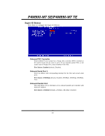
USB Device Setting
Press Enter to configure the USB Device.
USB 1.0/2.0 Controller
These options allow you to enable or disable the USB 1.0/2.0 controller
function.
The Choices: Enabled
(default), Disabled.