Biostar TFORCE4 SLI TForce4 SLI user's manual - Page 6
Hardware Installations - cpu
 |
View all Biostar TFORCE4 SLI manuals
Add to My Manuals
Save this manual to your list of manuals |
Page 6 highlights
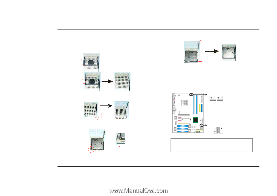
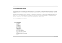
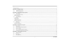
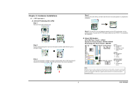
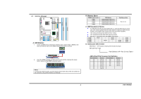
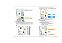
Biostar T-Series Chapter 2: Hardware Installations 2.1 CPU ASSEMBLY A. Central Processing Unit (CPU) Step 1: Remove the socket protection cap. Step 2: Pull the socket locking lever out from the socket and then raise the lever up to a 90-degree angle. Step 3: Look for the triangular cut edge on socket, and the golden dot on CPU should point towards this triangular cut edge. The CPU will fit only in the correct orientation. TForce4 SLI Step 4: Hold the CPU down firmly, and then lower the lever to locked position to complete the installation. Step 5: Put the CPU Fan and heatsink assembly on the CPU and buckle it on the retention frame. Connect the CPU FAN power cable into the JCFAN1. This completes the installation. B. About FAN Headers CPU FAN Power Header: JCFAN1 System Fan Power Headers: JSFAN1/JSFAN2 North Bridge Fan Power Header: JNBFAN1 JCFAN1JSFAN2 1313 JCFAN1: Pin Assignment 1 Ground 2 Smart Fan Control 3 FAN RPM rate sense JSFAN2: Pin Assignment 1 Ground 2 +12V 3 Ground JNBFAN1 JSFAN1 3 1 1 3 JNBFAN1/JSFAN1: Pin Assignment 1 Ground 2 +12V 3 Fan RPM rate Sense Note: JCFAN1 reserves system cooling fan with Smart Fan Control utilities. It supports 3 pin head connector. When connecting with wires onto connectors, please note that the red wire is the positive and should be connected to pin#2, and the black wire is Ground and should be connected to GND. 3 User's Manual
-
 1
1 -
 2
2 -
 3
3 -
 4
4 -
 5
5 -
 6
6 -
 7
7 -
 8
8 -
 9
9 -
 10
10 -
 11
11 -
 12
12 -
13
-
14
-
15
-
16
-
17
-
18
-
19
-
20
-
21
-
22
-
23
-
24
-
25
-
26
-
27
-
28
-
29
-
30
-
31
 |
 |