Biostar TFORCE4 SLI TForce4 SLI user's manual - Page 7
A. DDR Modules, B. Memory Space, C. DDR Installation Notice, D. Know your CPU Version - manual
 |
View all Biostar TFORCE4 SLI manuals
Add to My Manuals
Save this manual to your list of manuals |
Page 7 highlights
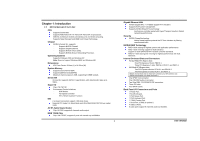
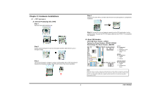
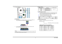
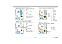
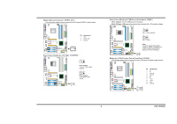
Biostar T-Series 2.2 SYSTEM MEMORY A. DDR Modules 1. Unlock a DIMM slot by pressing the retaining clips outward. Align a DIMM on the slot such that the notch on the DIMM matches the break on the slot. 2. Insert the DIMM vertically and firmly into the slot until the retaining chip snaps back in place and the DIMM is properly seated. Notes: To remove the DDR modules, push the ejector tabs at both sides of the slot outward at the same time, and pull the modules out vertically. DIMM2 DIMM4 DIMM1 DIMM3 TForce4 SLI B. Memory Space DIMM Socket Location DIMM1 DIMM2 DIMM3 DIMM4 DDR Module 128MB/256MB/512MB/1GB *1 128MB/256MB/512MB/1GB *1 128MB/256MB/512MB/1GB *1 128MB/256MB/512MB/1GB *1 Total Memory Size Max is 4 GB. C. DDR Installation Notice For AMD K8 939 CPU launched before Rev. E, (see the table below to know your CPU version) please follow the table below to install your DDR memory module, or the system may not boot up or may not function properly. "SS" represents Single Side DDR memory module. "DS" represents Double Side DDR memory module. Star sign "*" represents leave the DIMM socket empty. DIMM1 DIMM2 DIMM3 DIMM4 SS/DS * * * * * SS/DS * SS/DS SS/DS * * * * SS/DS SS/DS SS/DS SS/DS SS/DS SS/DS D. Know your CPU Version AMD Athlon™ 64 Processor Ordering Part Number Example ADA 3200 A E P 5 AP Part Definition: AP = Rev C0 (see Table 1) AMD Athlon™ 64 Processor Part Definition Part Definition AP AR AS AW AX AZ BI Revision Rev C0 Rev CG Rev CG Rev CG Rev CG Rev CG Rev D0 Part Definition BN BP BO BY BW Revision Rev E4 Rev E3 Rev E3 Rev E6 Rev E6 4 User's Manual
-
 1
1 -
 2
2 -
 3
3 -
 4
4 -
 5
5 -
 6
6 -
 7
7 -
 8
8 -
 9
9 -
 10
10 -
 11
11 -
 12
12 -
13
-
14
-
15
-
16
-
17
-
18
-
19
-
20
-
21
-
22
-
23
-
24
-
25
-
26
-
27
-
28
-
29
-
30
-
31
 |
 |
