Biostar TFORCE4 U TForce4 U user's manual - Page 12
JPANEL1: Header for Front Panel Facilities, LED Indicators and Buttons - memory
 |
View all Biostar TFORCE4 U manuals
Add to My Manuals
Save this manual to your list of manuals |
Page 12 highlights
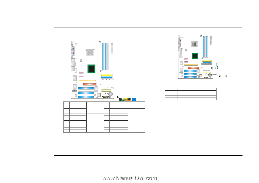
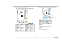
Biostar T-Series JPANEL1: Header for Front Panel Facilities This 24-pin connector includes Power-on, Reset, HDD LED, Power LED, Sleep button, speaker and IrDA Connection. It allows user to connect the PC case's front panel switch functions. TForce4/ TForce4 U LED Indicators and Buttons There are 4 LED indicators on the motherboard to show system status. Codec Pin Assignment 1 +5V 3 N/A 5 N/A 7 Speaker 9 HDD LED (+) 11 HDD LED (-) 13 Ground 15 Reset control 17 N/A 19 N/A 21 +5V 23 IRTX BIOS Function Speaker Connector Hard drive LED Reset button IrDA Connector JPANEL1 2 24 1 23 Pin Assignment Function 2 Sleep control 4 Ground Sleep button 6 N/A N/A 8 Power LED (+) 10 Power LED (+) Power LED 12 Power LED (-) 14 Power button 16 Ground Power-on button 18 Key 20 Key 22 Ground IrDA Connector 24 IRRX LED_D1 LED_D2 LED_DIMM LED_5SB PWRSW RSTSW Codec BIOS LED_D1 and LED_D2: These 2 LED indicate system power on diagnostics. Please refer to the table below for different messages: LED_D1 LED_D2 Message ON ON Normal ON OFF Memory Error OFF ON VGA Error OFF OFF CPU / Chipset Error LED_DIMM: This LED indicates the voltage of memory is activated normally. LED_5SB: This LED indicates the system is ready for Power-on. PWRSW: This is an on-board Power Switch button. RSTSW: This is an on-board Reset button. 10 User's Manual
-
 1
1 -
2
-
3
-
4
-
5
-
6
-
 7
7 -
 8
8 -
 9
9 -
 10
10 -
 11
11 -
 12
12 -
 13
13 -
 14
14 -
 15
15 -
 16
16 -
 17
17 -
18
-
19
-
20
-
21
-
22
-
23
-
24
-
25
-
26
 |
 |