Biostar U8668 U8668 user's manual
Biostar U8668 Manual
 |
View all Biostar U8668 manuals
Add to My Manuals
Save this manual to your list of manuals |
Biostar U8668 manual content summary:
- Biostar U8668 | U8668 user's manual - Page 1
installation. This equipment generates, uses and can radiate radio frequency energy and, if not installed and used in accordance with the instructions vendor's approval in writing. The content of this user's manual is subject to be changed without notice and we will not be responsible for any mistakes - Biostar U8668 | U8668 user's manual - Page 2
Features Introduction 2 1-1. Hardware ...2 1-2. BIOS & Software 6 1-3. Package Contents 6 2. Mainboard Configuration 7 2-1. Layout of U8668 7 2-2. Component Index 8 3. CPU Configuration 9 3-1. CPU Socket 478 Configuration Steps 9 3-2. CPU Fan Header: JCFAN1 10 3-3. System Fan Header: JSFAN1 - Biostar U8668 | U8668 user's manual - Page 3
/ 5VSB Selection for KB: JKBV1 18 5. RAM Module Configuration 19 5-1. DDR SDRAM 19 5-2. SDRAM...20 5-3. How to install DDR/SDRAM DIMM Module 21 6. Peripheral Port Game (Joystick/MIDI) Port Connector: JAUD_GAME 29 6-5. Audio Port Connectors: JSPKR1/JLIN1/JMIC1 29 6-6. Audio Subsystem 30 ii - Biostar U8668 | U8668 user's manual - Page 4
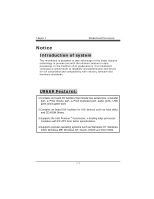
port, audio ports, USB ports and a game port. 2.Contains on board IDE facilities for IDE devices such as hard disks and CD-ROM Drives. 3.Supports the Intel Pentium ® 4 processor, a leading edge processor. Complies with PC ATX form factor specifications. 4.Supports popular operating systems such as - Biostar U8668 | U8668 user's manual - Page 5
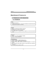
1 Motherboard Description Mainboard Features 1. Features Introduction 1-1. Hardware CPU: 1.Provides Socket-478. 2.Supports the Intel Pentium ® 4 processor providing the new generation power for high-end workstations and servers. Speed: 1.Runing at 400 MHz Front Side Bus frequency. 2.Supports up - Biostar U8668 | U8668 user's manual - Page 6
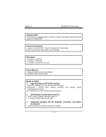
Chapter 1 Motherboard Description Shadow RAM: Motherboard is equipped with a memory controller providing shadow RAM and support for ROM BIOS. Green Functionality: 1.Supports Award BIOS ™ power management functionality. 2.Has a power down timer from 1 to 15 minutes. BUS Slots: 1.Contains 1 AGP slot - Biostar U8668 | U8668 user's manual - Page 7
Chapter 1 Motherboard Description 32.. F16lo/at3in2gM-pBoifnrat mtrieanbgulfefesreutusipngensgyisntee.m memory. 4. Single 1.Supports four IDE hard disk drives. 2.Supports PIO Mode 4, Master Mode, and high performance hard disk drives. 3.Supports disk transfer rates up to 133 MB/second. 4.Supports - Biostar U8668 | U8668 user's manual - Page 8
, 1.2MB, 1.44MB, and 2.88MB floppy disk drives. Universal Serial Bus: Supports two back panel Universal Serial Bus Ports and two front panel Universal Serial Bus Ports. Hardware Monitor Function: 1.Monitors CPU Fan Speed. 2.Monitors System Voltage. Dimensions (MATX form-factor): 24.5cm x 24.5cm (WxL - Biostar U8668 | U8668 user's manual - Page 9
BIOS. 2.Supports APM1.2. 3.Supports USB Function. 4.Supports ACPI. Operating System: Offers the highest performance for MS-DOS, Windows NT, Windows 2000, Windows ME, Windows XP, Novell, LINUX, and SCO UNIX etc. 1-3. Package Contents 1.HDD Cable. 2.FDD Cable. 3.Flash Memory Writer for BIOS Update - Biostar U8668 | U8668 user's manual - Page 10
Chapter 1 Motherboard Description 2. Mainboard Configuration 2-1. Layout of U8668 JKBMS1 K/B & Mouse 1 JLAN USB & LAN JCOM1 JKBV1 CPU1 Socket 478 CPU BAT1 COM1 Parallel Port VGA1 JPRNT1 JVGA1 J AT X P W SECONDARY IDE CONN. 24 23 FLOPPY DISK CONN. 1 JCMOS1 BIOS 21 JPANEL1 1-7 - Biostar U8668 | U8668 user's manual - Page 11
Chapter 1 Motherboard Description 2-2. Component Index 1-8 - Biostar U8668 | U8668 user's manual - Page 12
Chapter 1 Motherboard Description 3. CPU Configuration 3-1. CPU Socket 478 Configuration Steps: CPU Fan CPU 1. Pull the lever sideways away from the socket then raise the lever up to a 90-degree angle. 2. Locate Pin A in the socket and look for the white dot or cut edge in the CPU. Match Pin A - Biostar U8668 | U8668 user's manual - Page 13
Chapter 1 Motherboard Description CPU Configuration Layout 3-2. CPU Fan Header: JCFAN1 Pin No. 1 2 3 Assignment Ground +12V Sense 1-10 - Biostar U8668 | U8668 user's manual - Page 14
Chapter 1 Motherboard Description 3-3. System Fan Header: JSFAN1 (Optional) Pin No. 1 2 3 Assignment Ground +12V Sense 1-11 - Biostar U8668 | U8668 user's manual - Page 15
Chapter 1 Motherboard Description 4. Jumpers, Headers & Connectors 1 JKBV1 JATXPWR2 JCODECSEL 1 JWOL1 1 JUSB3 2 10 1 9 JCMOS1 1 JATXPWR1 IDE 1-2 FDD1 JPANEL1 24 23 21 1-12 - Biostar U8668 | U8668 user's manual - Page 16
speaker can be installed on the motherboard as a manufacturing option. An offboard speaker can be connected to the motherboard at the front interface. The speaker is not connected to the audio subsystem and does not receive output from the audio subsystem. RST (Reset Button) This connector can be - Biostar U8668 | U8668 user's manual - Page 17
1 Motherboard Description only applies to those IDE drives directly attached to the system board. IR (Infrared Connector) This connector is used to attach . APM (Advanced Power Management) must be enabled in the system BIOS and the APM driver must be loaded. ON/OFF (Power Button) This connector can - Biostar U8668 | U8668 user's manual - Page 18
Chapter 1 Motherboard Description 4-2. ATX 20-pin Power Connector: JATXPWR1 PIN 1 2 3 4 5 6 7 8 9 10 Assignment 3.3V 3.3V Ground 5V Ground 5V Ground PW_OK 5V_SB 12V PIN 11 12 13 14 - Biostar U8668 | U8668 user's manual - Page 19
Chapter 1 Motherboard Description 4-4. Hard Disk Connectors: IDE1/IDE2 This mainboard has a 32-bit Enhanced PCI IDE Controller FDD1 The motherboard provides a standard floppy disk connector (FDC) that supports 360K, 720K, 1.2M, 1.44M and 2.88M floppy disk types. This connector supports the provided - Biostar U8668 | U8668 user's manual - Page 20
Chapter 1 Motherboard Description 4-7. Clear CMOS Jumper: JCMOS1 JCMOS1 1 3 1-2 Closed 1 3 2-3 Closed Assignment Normal Operation (default) Clear CMOS Data The following procedures are for resetting the BIOS password. It is important to follow these instructions closely. ※ Clear CMOS - Biostar U8668 | U8668 user's manual - Page 21
Chapter 1 Motherboard Description 4-9. Front USB Header: JUSB3 (with USB1.0 spe) (JUSB3) Pin 1 3 5 7 9 Assignment +5V(fused) USBP2USBP2+ Ground KEY Pin Assignment 2 +5V(fused) 4 USBP3- 6 USBP3+ 8 Ground 10 NC 4-10. 5V / 5VSB Selection for KB: JKBV1 JKBV1 1 3 1-2 Closed 1 3 - Biostar U8668 | U8668 user's manual - Page 22
Chapter 1 Motherboard Description 5. RAM Module Configuration 5-1. DDR SDRAM DRAM Access Time: 2.5V Unbuffered DDR SDRAM PC1600/ PC2100 Type required. DRAM Type: 128MB/ 256MB/ 512MB/ 1GB DIMM Module (184 pin) - Biostar U8668 | U8668 user's manual - Page 23
Mainboard Features 5-2. SDRAM DRAM Access Time: 3.3V Unbuffered SDRAM PC100/ PC133 Type required. DRAM Type: 128MB/ 256MB/ 512MB/ 1GB DIMM Module (168 pin) Total Memory Size - Biostar U8668 | U8668 user's manual - Page 24
Mainboard Features 5-3. How to install DDR/SDRAM DIMM Module DDR SDRAM: Single Sided DIMM Double Sided DIMM 1. The DDR DIMM socket has a " direction. 2. Push the tabs out. Insert the DDR DIMM memory modules into the socket at a 90-degree angle, then push down vertically so that it will fit into - Biostar U8668 | U8668 user's manual - Page 25
SDRAM: Mainboard Features 1. The SDRAM DIMM socket has a " Plastic Safety Tab", and the SDRAM DIMM memory module has an Asymmetrical notch", so the SDRAM DIMM memory module can only fit into the slot in one direction. 2. Push the tabs out. Insert the SDRAM DIMM memory modules into the socket at a - Biostar U8668 | U8668 user's manual - Page 26
Mainboard Features 6. Peripheral Port Features JKBMS1 PS/2 JUSBLAN1 Mouse LAN JPRNT1 Parallel JAUD_GAME Game Port PS/2 Keyboard USB COM1 JCOM1 VGA1 Speaker Out Line In Mic In JVGA1 JSPKR1 JLIN1 JMIC1 6-1. PS/2 Mouse / Keyboard Connector: JKBMS1 The motherboard provides a standard PS/2 - Biostar U8668 | U8668 user's manual - Page 27
Mainboard Features 6-2. USB & LAN Port Connectors: JUSBLAN1 6-2-1. USB Connectors: USB Connector (the below one) Pin 1 2 3 4 USB Connector (the above one) Pin 5 6 7 8 Assignment +5 V (fused) USBP1USBP1+ Ground Assignment +5 V (fused) USBP2USBP2+ Ground 24 - Biostar U8668 | U8668 user's manual - Page 28
Mainboard Features 6-2-2. LAN Port Connector This connector allows you to connect to the Internet through a Local Area Network (LAN). You can set up the connection by entering account information provided by your ISP. LAN Port Connector Pin 9 10 11 12 13 14 Assignment VCC3 TD+ TDRD+ RDNC 25 - Biostar U8668 | U8668 user's manual - Page 29
Mainboard Features 6-3. Serial and Parallel Interface Ports This system comes equipped with two serial ports and one serial port. The serial port can also be used to connect your computer with another computer system. Connectivity The serial ports can be used in many ways, and it may be necessary - Biostar U8668 | U8668 user's manual - Page 30
Mainboard Features 6-3-2Video Graphics Adapter Port: JVGA1 This motherboard has built in video facilities. Your monitor will attach directly to JVGA1 connector on the motherboard. 5 1 15 11 JVGA1 Pin No. Assignment Pin No. Assignment 1 Red 2 Green 3 Blue 4 NC 5 Ground 6 Ground - Biostar U8668 | U8668 user's manual - Page 31
Mainboard Features 6-3-3. Parallel Interface Port: JPRNT1 Unlike the serial ports, parallel interface port has been standardized and should not present any difficulty interfacing peripherals to your system. Sometimes called centronics port, the parallel port is almost exclusively used with printers - Biostar U8668 | U8668 user's manual - Page 32
Mainboard Features 6-4. Game (Joystick/MIDI) Port Connector: JAUD_GAME This connector allows you to connect a joystick or game pad for playing computer games. Also, you may play or edit professional music by connecting MIDI devices. Game/Joystick/MIDI 6-5. Audio Port Connectors: JSPKR1/JLIN1/JMIC1 - Biostar U8668 | U8668 user's manual - Page 33
6-6. Audio Subsystem Mainboard Features JAUDIO1 2 10 1 9 J TA D 1 1 JCDIN2 1 1 J C D IN 1 30 - Biostar U8668 | U8668 user's manual - Page 34
Mainboard Features 6-6-1. CD-ROM Audio-In Header: JCDIN1 Pin No. 1 2 3 4 Assignment Left Channel Input Ground Ground Right Channel Input 6-6-2. CD-ROM Audio-In Header: JCDIN2 Pin No. 1 2 3 4 Assignment Left Channel Input Ground Right Channel Input Ground 6-6-3. Front Panel Audio Header: - Biostar U8668 | U8668 user's manual - Page 35
04/9/2002
-
 1
1 -
 2
2 -
 3
3 -
 4
4 -
 5
5 -
 6
6 -
 7
7 -
8
-
9
-
10
-
11
-
12
-
13
-
14
-
15
-
16
-
17
-
18
-
19
-
20
-
21
-
22
-
23
-
24
-
25
-
26
-
27
-
28
-
29
-
30
-
31
-
32
-
33
-
34
-
35
 |
 |

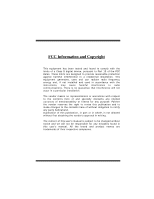
FCC Information and Copyright
This equipment has been tested and found to comply with the
limits of a Class B digital device, pursuant to Part 15 of the FCC
Rules. These limits are designed to provide reasonable protection
against harmful interference in a residential installation. This
equipment generates, uses and can radiate radio frequency
energy and, if not installed and used in accordance with the
instructions,
may
cause
harmful
interference
to
radio
communications. There is no guarantee that interference will not
occur in a particular installation.
The vendor makes no representations or warranties with respect
to the contents here of and specially disclaims any implied
warranties
of merchantability or fitness for any purpose. Further
the vendor reserves the right to revise this publication and to
make changes to the contents here of without obligation to notify
any party beforehand.
Duplication of this publication, in part or in whole, is not allowed
without first obtaining the vendor’s approval in writing.
The content of this user’s manual is subject to be changed without
notice and we will not be responsible for any mistakes found in
this user’s manual. All the brand and product names are
trademarks of their respective companies.