Black & Decker HH2455 Type 1 Manual - HH2455 - Page 3
SPECIFIC SAFETY WARNING, Extension Cords - hedge trimmer
 |
View all Black & Decker HH2455 manuals
Add to My Manuals
Save this manual to your list of manuals |
Page 3 highlights
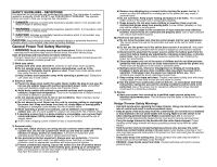
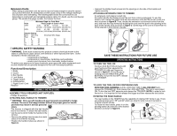
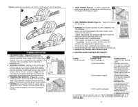
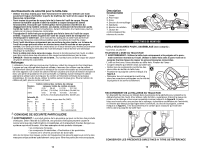
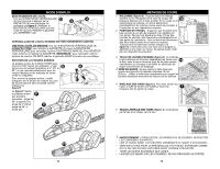
Extension Cords When using an extension cord, be sure to use one heavy enough to carry the current your product will draw. An undersized cord will cause a drop in line voltage resulting in loss of power and overheating. The following table shows the correct size to use depending on cord length and nameplate ampere rating. If in doubt, use the next heavier gauge. The smaller the gauge number, the heavier the cord. Minimum Gage for Cord Sets Volts Total Length of Cord in Feet 120V 0-25 26-50 51-100 101-150 (0-7,6m) (7,6-15,2m) (15,2-30,4m) (30,4-45,7m) 240V 0-50 51-100 101-200 201-300 (0-15,2m) (15,2-30,4m) (30,4-60,9m) (60,9-91,4m) Ampere Rating More Not more American Wire Gage Than Than 0 -6 18 16 16 14 6 - 10 18 16 14 12 10 - 12 16 16 14 12 12 - 16 14 12 Not Recommended SPECIFIC SAFETY WARNING WARNING: Some dust created by this product contains chemicals known to the State of California to cause cancer, birth defects or other reproductive harm. Some examples of these chemicals are: • compounds in fertilizers • compounds in insecticides, herbicides and pesticides • arsenic and chromium from chemically treated lumber To reduce your exposure to these chemicals, wear approved safety equipment such as dust masks that are specially designed to filter out microscopic particles. Functional Description 1. Blade 2. Guard 3. Bail Handle 3 4. Lock Button 2 5. Trigger Switch 6. Rotate Button 7. Pigtail Cord / Cord 1 Retainer 4 5 7 6 ASSEMBLY INSTRUCTIONS ASSEMBLY TOOLS REQUIRED (NOT SUPPLIED): - Phillips Screwdriver ATTACHING BAIL HANDLE TO TRIMMER WARNING: Only use with handle and guard properly assembled to hedge trimmer. The use of the hedge trimmer without the proper guard or handle provided may result in serious personal injury. A The trimmer is shipped with the bail handle tied to the trimmer. To attach the bail handle: • Cut the zip tie which holds the handle to the trimmer. • Remove the phillips head screws from both sides of the trimmer housing. • Position the handle in place as shown in figure A. 4 • Reinsert the phillips head screws into the openings on the side of the handle and tighten securely. ATTACHING EXTENSION CORD TO TRIMMER An extension cord retainer is built into the switch handle that helps prevent the tool from coming unplugged. To use this feature, first overlap the pigtail cord with the extension cord and tie the two cords in a knot as shown in figure B. Then, double the extension cord several inches from the end, and hook the loop formed by doubling the cord over the post in the opening in the back of the handle area as shown in figure C. Gently tug on the cord to insure that it is firmly retained in the trimmerʼs handle. B C SAVE THESE INSTRUCTIONS FOR FUTURE USE OPERATING INSTRUCTIONS TO TURN THE TOOL ON Pull the LOCK BUTTON (4) back with D your thumb and then squeeze the 5 4 TRIGGER (5) with your fingers as shown in figure D. (Once the tool is running you can release the LOCK BUTTON.) To turn the tool OFF, release the TRIGGER. TO LOCK THE TOOL ON FOR CONTINUOUS RUN WITH THE TOOL RUNNING, pull the LOCK BUTTON (4) ALL THE WAY back, release the TRIGGER (5), then release the LOCK BUTTON. The tool is now locked ON. To turn the tool OFF, squeeze and release the TRIGGER. NOTE: In order to lock the tool on, it is important to first release the trigger and then release the lock button. ROTATING THE REAR HANDLE The rear handle on the HH2455 has the capability of rotating 180° while in use. There are optional stops at 0°, 55° and 90° which are ideal for side cuts and rounded or irregular shaped shrubs. E To rotate the rear handle, press in on the pivoting button (6) and turn in the desired 6 direction as shown in figure E. 5
-
 1
1 -
 2
2 -
 3
3 -
 4
4 -
 5
5 -
 6
6 -
 7
7 -
 8
8 -
 9
9 -
10
-
11
-
12
-
13
-
14
-
15
 |
 |
