Bosch 1347A Operating Instructions - Page 7
Assembly - flange and nut
 |
UPC - 000346017571
View all Bosch 1347A manuals
Add to My Manuals
Save this manual to your list of manuals |
Page 7 highlights
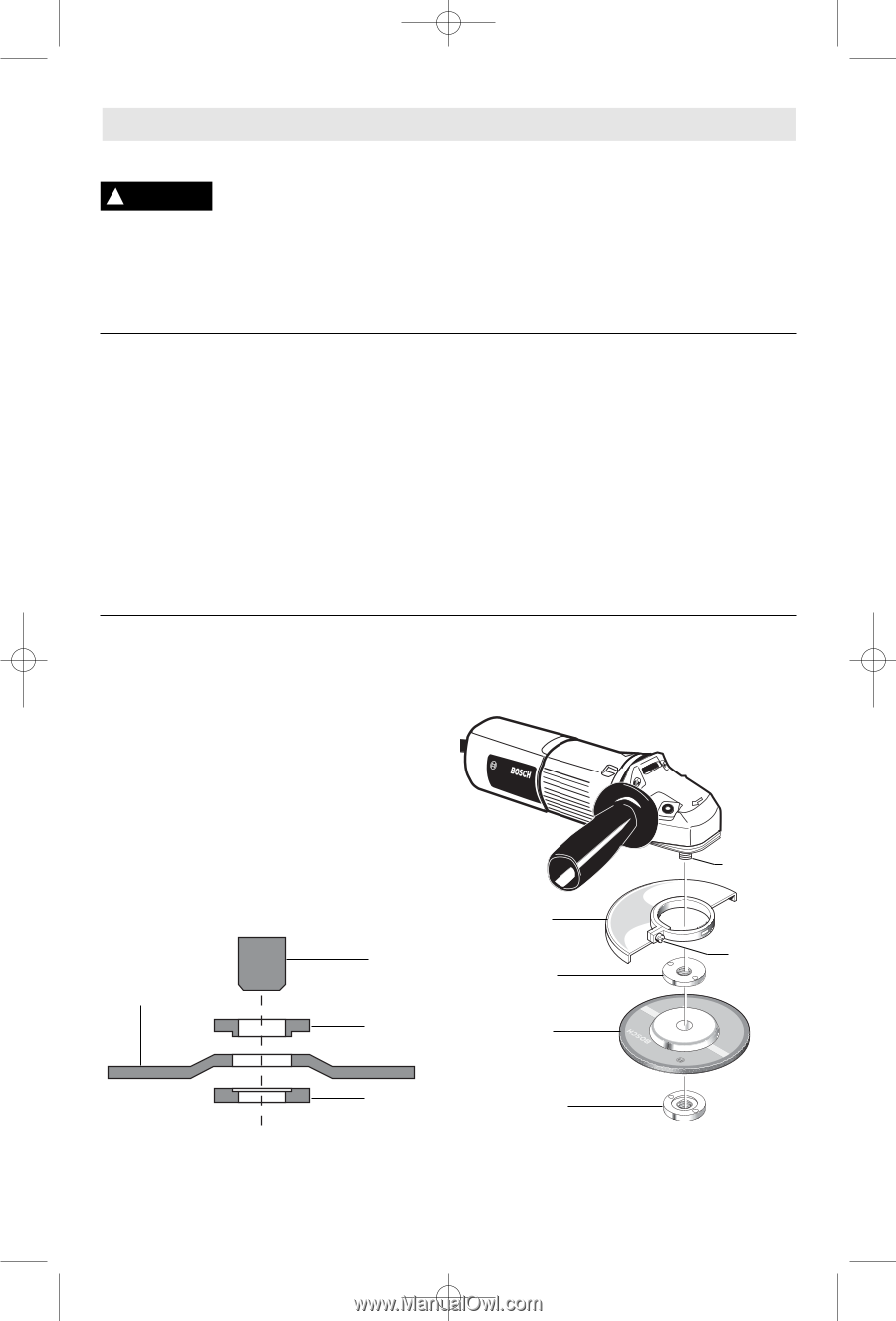
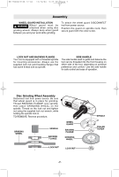
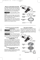
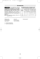
BM F000622188 12-04 12/10/04 9:27 PM Page 7 Assembly WHEEL GUARD INSTALLATION ! WARNING Wheel guard must be attached when using disc grinding wheels. Always keep wheel guard between you and your work while grinding. To attach the wheel guard DISCONNECT tool from power source. Position the guard on spindle neck, then secure guard with the collar screw. LOCK NUT AND BACKING FLANGE Your tool is equipped with a threaded spindle for mounting accessories. Always use the supplied lock nut (and backing flange) that has same thread size as spindle. SIDE HANDLE The side handle used to guide and balance the tool can be threaded into the front housing on either side of the tool, depending on personal preference and comfort. Use the side handle for safe control and ease of operation. Disc Grinding Wheel Assembly Disconnect tool from power source. Be sure that wheel guard is in place for grinding. Thread BACKING FLANGE onto spindle, then place GRINDING WHEEL on the spindle. Thread on the lock nut and tighten nut using the supplied lock nut wrench, while holding the spindle lock in. TO REMOVE: Reverse procedure. GRINDING WHEEL SPINDLE BACKING FLANGE WHEEL GUARD BACKING FLANGE GRINDING WHEEL LOCK NUT LOCK NUT -7- SPINDLE COLLAR SCREW
-
 1
1 -
 2
2 -
 3
3 -
 4
4 -
 5
5 -
 6
6 -
 7
7 -
 8
8 -
 9
9 -
 10
10 -
 11
11 -
 12
12 -
13
-
14
-
15
-
16
-
17
-
18
-
19
-
20
-
21
-
22
-
23
-
24
-
25
-
26
-
27
-
28
-
29
-
30
-
31
-
32
-
33
-
34
-
35
-
36
 |
 |