Bosch 3814 Operating Instructions - Page 6
Operating Instructions
 |
UPC - 000346303483
View all Bosch 3814 manuals
Add to My Manuals
Save this manual to your list of manuals |
Page 6 highlights
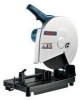
Operating Instructions TRIGGER SWITCH WITH "LOCK-ON" BUTTON Your tool can be turned "ON" or "OFF" by squeezing or releasing the trigger. Your tool is also equipped with "Lock-ON" button, located on the left side of the trigger handle, that allows for continuous operation without holding the trigger. The "LockON" is a convenience for long cutting operations. NOTE: Switch can accommodate a padlock with a shackle of up to 3/16" in diameter (not provided with tool) to prevent unauthorized use. TO LOCK SWITCH ON: Squeeze trigger, depress button and release trigger. TO UNLOCK THE SWITCH: Squeeze trigger and release it without depressing the "Lock-ON" button. ! WARNING If the "Lock-ON" button is continuously being depressed, the trigger cannot be released. FIG. 2 "LOCK-ON" BUTTON TRIGGER SWITCH ! WARNING To prevent serious personal injury, always disconnect the plug for the power source before changing wheels, or making any adjustments on the tool. Removing and Installing Wheels 1. Raise wheel guard as shown in (Fig. 3), push in spindle lock (Fig. 1), and loosen the hex head bolt in the center of abrasive wheel by rotating counter-clockwise with the wrench provided. 2. Remove the hex head bolt, outside flange and abrasive wheel (Fig. 3). 3. Carefully install the new abrasive wheel onto the spindle shaft and replace outside flange and hex head bolt. 4. Press in spindle lock and tighten hex bolt with the wrench provided (ATTENTION: DO NOT OVERTIGHTEN). ! WARNING Whenever replacing a wheel, always adjust the depth stop bolt to prevent the wheel from cutting into the surface the tool is resting on. Failure to make this adjustment may result in serious personal injury. FIG. 3 SPINDLE SHAFT WHEEL GUARD ABRASIVE WHEEL INSIDE RETAINING FLANGE RING OUTSIDE FLANGE DEPTH STOP ADJUSTMENT BOLT LOCK NUT SPACER (THINNER) ADAPTER (THICKER) HEX HEAD BOLT -6-
-
 1
1 -
 2
2 -
 3
3 -
 4
4 -
 5
5 -
 6
6 -
 7
7 -
 8
8 -
 9
9 -
 10
10 -
 11
11 -
 12
12 -
13
-
14
-
15
-
16
-
17
-
18
-
19
-
20
-
21
-
22
-
23
-
24
 |
 |
