Bosch NGM5024UC Installation Instructions - Page 7
Install the Cooktop, Connect Gas Supply - security
 |
UPC - 825225858355
View all Bosch NGM5024UC manuals
Add to My Manuals
Save this manual to your list of manuals |
Page 7 highlights
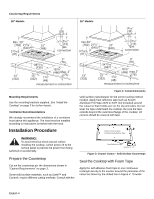
Cutout - Foam Tape Placement". Leave 1/4" (6.35mm) gap between the foam tape and the edge of the cutout. Cutout 1/4" (6.35mm) Foam Tape Connect Gas Supply The gas inlet to the unit is located at the right rear of roughin box. Opening for Gas Connection and Electrical Cord Figure 4: Counter Cutout - Foam Tape Placement Install the Cooktop Insert cooktop into the cutout. Attach clamps of the holddown brackets packaged with the cooktop to the rough-in box. Use the washer and screws provided. Rough-in Box Clamp Foam Tape (Seal) Adjusting Screw Adjusting Screw Wooden Block (to be used with solid surfacing material, i.e. Surell™ and Corian®) Clamp 1" CL of Cutout for 30" models: 12 15/16" (313 mm) for 36" models: 15 15/16" (389 mm) Figure 6: Rough-in Box Area Install the pressure regulator (supplied with unit) to manifold pipe using Teflon tape on threads of manifold pipe. Turn to hand tighten plus 1/4 turn, not exceeding 1 turn for alignment. To prevent possible damage to the gas pressure regulator, install it after the rough-in box is in its permanent position. When the regulator is securely installed on the manifold pipe, the conversion nut will be easily accessible. Figure 5: Attaching Hold-Down Brackets Adjust hold-down brackets to desired position and tighten screws to rough-in box. Insert adjusting screw into clamp and secure cooktop to countertop. NOTE: For solid surface material installations: Insert a wooden block between the end of the screw and the bottom of the countertop. Do not overtighten adjusting screw. Trim excess aluminum tape around cooktop flange. Figure 7: Pressure Regulator CAUTION: Do not attempt any adjustment of the pressure regulator, except conversion to propane. Connect the gas supply line to the unit pressure regulator using a 1/2" flex gas line connector between manual shut- English 5
-
 1
1 -
 2
2 -
 3
3 -
 4
4 -
 5
5 -
 6
6 -
 7
7 -
 8
8 -
 9
9 -
 10
10 -
 11
11 -
 12
12 -
13
-
14
-
15
-
16
-
17
-
18
-
19
-
20
-
21
-
22
-
23
-
24
-
25
-
26
-
27
-
28
-
29
-
30
-
31
-
32
 |
 |
