Bose 2.2 Series II Owner's guide - Page 4
amplifier.
 |
View all Bose 2.2 Series II manuals
Add to My Manuals
Save this manual to your list of manuals |
Page 4 highlights
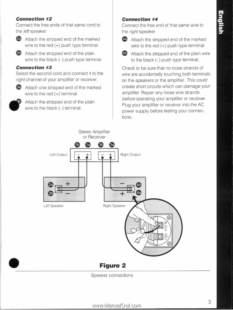
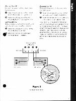
Connection #2 Connect the free ends of that same cord to the left speaker. Attach the stripped end of the marked wire to the red (+) push type terminal. Attach the stripped end of the plain wire to the black (-) push type terminal. Connection #3 Select the second cord and connect it to the right channel of your amplifier or receiver. Attach one stripped end of the marked wire to the red (+) terminal. Attach the stripped end of the plain wire to the black (-) terminal. Connection #4 ta Connect the free end of that same wire to the right speaker. Attach the stripped end of the marked wire to the red (+) push type terminal. Attach the snipped end of the plain wire to the black (-) push type terminal. Check to be sure that no loose strands of wire are accidentally touching both terminals on the speakers or the amplifier. This could create short circuits which can damage your amplifier. Repair any loose wire strands before operating your amplifier or receiver. Plug your amplifier or receiver into the AC power supply before testing your connec- tions. Lett Output Stereo Amplifier or Receiver (Dee. Right Output Left Speaker Right Speaker A O • Figure 2 Speaker connections. 3
-
 1
1 -
 2
2 -
 3
3 -
 4
4 -
 5
5 -
 6
6 -
 7
7 -
 8
8 -
 9
9
 |
 |