Bose 321 GS Owner's guide - Page 16
Attaching the supplied antennas - speakers stands
 |
View all Bose 321 GS manuals
Add to My Manuals
Save this manual to your list of manuals |
Page 16 highlights
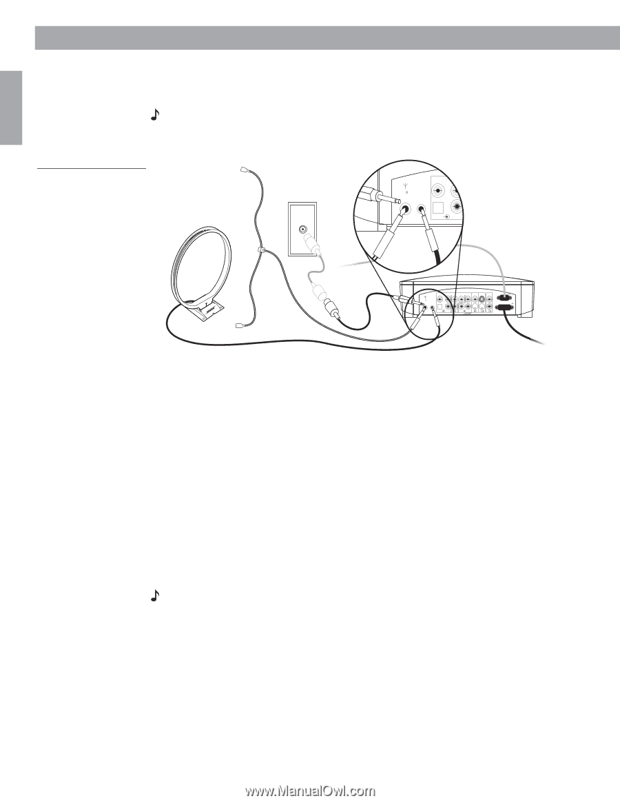
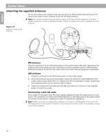
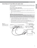
English System Setup Attaching the supplied antennas On the rear panel of the media center there are jacks for AM and FM antennas (Figure 15). Unwind the wires for each antenna to provide the best reception. Note: An outdoor antenna may be used in place of the two that are supplied. To add an outdoor antenna, consult a qualified installer. Follow all safety instructions supplied with the antenna. Figure 15 Adding the AM and FM antennas A VIDEO D L 75 1 FM AM LOOP ANTENNA ANTENNA OPTICAL R AM FM 220-240V FM VIDEO D L 75 1 FM AM LOOP ANTENNA ANTENNA OPTICAL R AUDIO INPUT IDEO 2 L D R D AUX L VIDEO INPUT C VIDEO AUDIO OUTPUT OUTPUT C L SPEAKERS R S S R ACOUSTIMASS MODULE FM antenna Plug the connector into the FM antenna jack on the media center rear panel. Spread out the antenna arms at the other end and move them around to establish optimum FM reception. Extend the antenna as far from the media center and other external equipment as possible. AM antenna 1. Plug the connector into the AM antenna jack on the media center. 2. Move the antenna loop as far as possible, at least 20 inches (50 centimeters) from the media center and at least 4 feet (1.2 meters) from the Acoustimass® module. Experiment with positioning the loop for optimum AM reception. 3. Follow the instructions enclosed with the AM loop antenna to stand it on the supplied base, or mount it to a wall. Connecting cable FM radio Some cable TV providers make FM radio signals available through the cable service to your home. This connection is made to the external FM jack on the back panel of the media center. To connect to this service, contact your cable TV provider for assistance. Note: Make sure that the cable radio installation includes a TV/FM splitter so that only the FM radio band, not the cable TV band, is received by the media center. If necessary, contact your cable company. 16 AM271966_00_V.pdf August 18, 2003
-
 1
1 -
2
-
3
-
4
-
5
-
6
-
7
-
8
-
9
-
10
-
 11
11 -
 12
12 -
 13
13 -
 14
14 -
 15
15 -
 16
16 -
 17
17 -
 18
18 -
 19
19 -
 20
20 -
 21
21 -
22
-
23
-
24
-
25
-
26
-
27
-
28
-
29
-
30
-
31
-
32
-
33
-
34
-
35
-
36
-
37
-
38
-
39
-
40
-
41
-
42
-
43
-
44
-
45
-
46
-
47
-
48
-
49
-
50
-
51
-
52
-
53
-
54
-
55
-
56
-
57
-
58
-
59
-
60
-
61
-
62
-
63
-
64
 |
 |