Bose 321 Owner's guide - Page 13
Making the connections, Follow these basic steps - fm antenna
 |
UPC - 017817493475
View all Bose 321 manuals
Add to My Manuals
Save this manual to your list of manuals |
Page 13 highlights
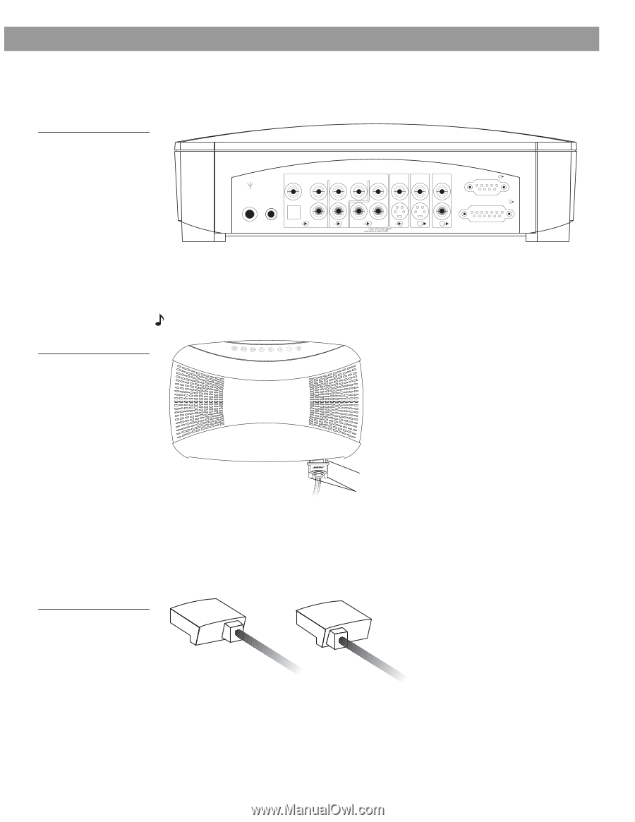
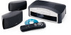
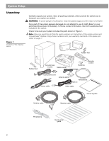
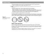
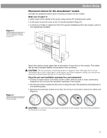
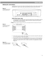
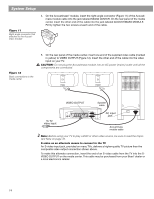
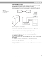
System Setup Making the connections Labeled jacks on the rear of the media center (Figure 8) and the custom cables supplied with the Model 3•2•1 system make it easy to get everything hooked up right the first time. Figure 8 Connection panel on the rear of the media center VIDEO 1 D L 75 Ω FM AM LOOP ANTENNA ANTENNA OPTICAL R AUDIO INPUT VIDEO 2 L D R D AUX L VIDEO INPUT C VIDEO OUTPUT C AUDIO OUTPUT L R S S R SPEAKERS ACOUSTIMASS MODULE Figure 9 Completed connection of speaker cable to media center rear panel Stop/Eject Skip/Scan Source Volume Power Follow these basic steps 1. On the rear panel of the media center, insert the single-plug end of the speaker cable into the SPEAKERS connector (Figure 8). Tighten the screws on either side of the plug to ensure a snug connection (Figure 9). Note: When properly inserted, there will be a small gap between the plug and the panel. Figure 10 LEFT and RIGHT markings on the speaker connectors Gap Screws 2. At the other end of the speaker cable, grasp the two connectors and pull the cable apart as much as necessary to reach each speaker. 3. Plug the LEFT connector of the separated cable into the rear jack on the left speaker (to the left of the TV as you face it) and the RIGHT connector into the rear jack on the right speaker (to the right of the TV). LEFT or RIGHT is printed on the appropriate connector (Figure 10). RIGHT LEFT AM256950_02_V.pdf • January 29, 2002 13
-
 1
1 -
2
-
3
-
4
-
5
-
6
-
7
-
 8
8 -
 9
9 -
 10
10 -
 11
11 -
 12
12 -
 13
13 -
 14
14 -
 15
15 -
 16
16 -
 17
17 -
 18
18 -
19
-
20
-
21
-
22
-
23
-
24
-
25
-
26
-
27
-
28
-
29
-
30
-
31
-
32
-
33
-
34
-
35
-
36
-
37
-
38
-
39
-
40
-
41
-
42
-
43
-
44
 |
 |