Bose 901 Series VI Loud Owner's guide - Page 10
Home theater use
 |
View all Bose 901 Series VI Loud manuals
Add to My Manuals
Save this manual to your list of manuals |
Page 10 highlights
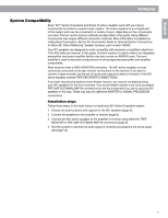
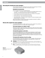
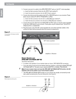
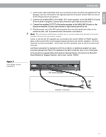
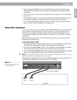
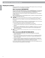
English Setting Up Figure 5 Connecting to the tape monitor connection 3. Connect one end of a cable to the AMPLIFIER INPUT jacks on the 901® active equalizer. a. Insert the first connector firmly into the INPUT jack marked R. b. Insert the second connector into the INPUT jack marked L. 4. Connect the other end of the cable to the OUT or RECORD jacks on your receiver. These jacks may be marked TO INPUT, FROM INPUT, or REC. a. Insert the first connector into the OUT or RECORD jack marked R. b. Insert the second connector into the OUT or RECORD jack marked L. 5. Connect the second cable from the AMPLIFIER OUTPUT jacks on the 901 active equalizer to the IN or TAPE jacks on your receiver. These jacks may be marked PLAY, TO OUTPUT, FROM OUTPUT, or MONITOR. 6. Plug the power cord of the 901 active equalizer into one of the switched outlets on the receiver so that it will be powered when the receiver is switched on. Figure 6 Removing horseshoe pins Home theater use (PRE AMP OUT/MAIN AMP IN) Use these instructions: • for stereo-only operation if your receiver does not have a TAPE MONITOR connection. • if you are using a surround sound receiver that has a section on the back marked PRE AMP OUT/MAIN AMP IN. The jacks may be labeled ADAPTER or SIGNAL PROCESSOR. Note: If your receiver does not have this PRE AMP OUT/MAIN AMP IN section, the 901 901.E. SERIAL 254818 OUTPUT AMPLIFIER CONNECTIONS INPUT OUTPUT TAPE RECORDER CONNECTIONS INPUT 120V AC 60Hz 2.5W LISTED 917D UL speakers will not be usable in your home theater system. R L ( TO AMP "TAPE IN" ) R L ( FROM AMP "TAPE OUT" ) R L ( TO REC "INPUT" ) R L ˆII¨ ( FROM REC "OUTPUT" ) AUDIO EQUIPMENT ENGINEERED IN U.S.A. BY BOSE CORPORATION FRAMINGHAM, MA 01701-9168 ASSEMBLED IN MEXICO 1. The PRE AMP OUT/MAIN AMP IN jacks on your receiver are usually connected by small bars c9a0lle1d® AhcotrivseesEhqouealpizienrs. Remove these pins. See Figure 6. Amplifier or Receiver MAIN AMP IN PRE AMP OUT L L R R 10
-
 1
1 -
2
-
3
-
4
-
 5
5 -
 6
6 -
 7
7 -
 8
8 -
 9
9 -
 10
10 -
 11
11 -
 12
12 -
 13
13 -
 14
14 -
 15
15 -
16
-
17
-
18
-
19
-
20
 |
 |