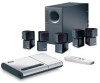
Bose Lifestyle 12 Owner's guide - Page 18
Connect the antennas, Attach the wire cover - speaker wire
 |
View all Bose Lifestyle 12 manuals
Add to My Manuals
Save this manual to your list of manuals |
Page 18 highlights
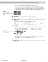
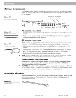
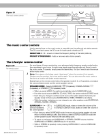
Setting Up Connect the antennas The rear panel of your Lifestyle® music center provides connections for AM and FM antennas (Figure 13). Unwind each antenna's wires. Antennas provide better reception when their wires are not bundled. Figure 13 The antenna connections FM antenna AM antenna jack terminals ® LIFESTYLE ® MODEL 5 MUSIC CENTER B Z G642 950 D S T BOSE Corporation UL LISTED 917D AUDIO ® EQUIPMENT MANUFACTURED: TÜV Rheinland BOSE CORPORATION, FRAMINGHAM, MA 01701-9168 MADE IN USA geprüdfte Sicherheit SPEAKERS L FIXED R 93 A B OUTPUT TAPE AUX VIDEO SOUND L R REC PLAY INPUT AM LOOP ANTENNA SYSTEM CONTROL 1 ~ POWER 12VAC IN 1.0A 2 Figure 14 The FM dipole antenna Figure 15 The AM loop antenna FM antenna connections 1. Plug the antenna connector into the FM ANTENNA jack on the back of the Lifestyle® music center. 2. Spread out the antenna arms. Experiment with both the placement and the angle of this antenna to provide optimum FM reception. AM antenna connections Note: To install the AM antenna on a wall, follow the instructions enclosed with the antenna. 1. Loosen the AM ANTENNA screw terminals on the back of the Lifestyle® music center. 2. Slide the wire connectors around the screw terminals. Tighten the screws over the connectors. 3. Stand the loop antenna on the base, following the instructions enclosed with the antenna. 4. Move the loop part of the antenna at least 20 inches (50 cm) from the music center. Experiment with the orientation of the loop for optimum AM reception. Note: Outdoor antennas may be used with the music center antenna connections. To install an outdoor antenna, consult a qualified installer. Follow all safety instructions. Connecting to a cable radio signal To connect your system to the FM signal available from some cable TV companies, contact your cable provider for assistance. The connection is made to the FM 75Ω EXTERNAL antenna connector on the back of the system. CAUTION: Be certain that the installation includes a signal splitter so that only the FM band, not the cable TV band, is transmitted to the system. It is necessary to use a splitter that filters the signal to prevent any re-emissions of the TV spectrum through the system. Attach the wire cover To hide the wires and jacks from view, after all the connections are completed, attach the wire cover to the music center. The five tabs on the wire cover snap into matching slots on the music center back panel. Figure 16 The wire cover 16 December 20, 2001 AM191409_01_V.pdf
-
 1
1 -
2
-
3
-
4
-
5
-
6
-
7
-
8
-
9
-
10
-
11
-
12
-
 13
13 -
 14
14 -
 15
15 -
 16
16 -
 17
17 -
 18
18 -
 19
19 -
 20
20 -
 21
21 -
 22
22 -
 23
23 -
24
-
25
-
26
-
27
-
28
-
29
-
30
-
31
-
32
-
33
-
34
 |
 |
