Bose Lifestyle 900 Owner's guide - Page 10
Connecting, Acoustimass, module, Lifestyle, music, center
 |
View all Bose Lifestyle 900 manuals
Add to My Manuals
Save this manual to your list of manuals |
Page 10 highlights
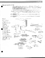
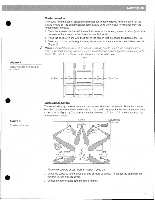
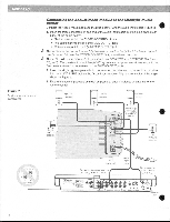
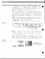
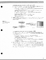
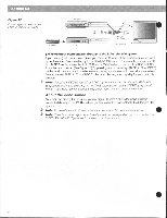
rye e ct ,j ..,2611•1, 7-.41/7":: Figure 7 Music center and speaker connections Fe eh ica,S1i7430:;•1;;;C:%',i Connecting the Acoustimass' module to the Lifestyle' music center Connect the Acoustimass module to the music center with the audio input cable (Figure 7). 1. Insert the three connectors at one end of the audio input cable into the jacks on the rear panel of the music center: • Black connector into the SYSTEM CONTROL 1 jack • Red connector into the R (right) FIXED OUTPUT jack • White connector into the L (left) FIXED OUTPUT jack Note: Be sure the connectors are fully inserted into each of the jacks. If the black connector is not inserted fully into the SYSTEM CONTROL jack, you will hear no sound. Note: Do not connect the audio input cable to the SPEAKERS A or SPEAKERS B outputs {Figure 7). The speakers in your Lifestyle 900 system are designed to work properly with the fixed level audio output available from the FIXED OUTPUT jacks. 2. Insert the single right-angle multi-pin connector on the other end of the audio input cable into the AUDIO INPUT jack on the Acoustimass module. Align the connector at the angle shown in Figure 7. 3. Extend the audio input cable as much as possible, since it includes an antenna for the remote control. Right front speaker Center taro , speaker Left front speaker • L Right-angle O:nneCtor into AUDIO • INPUT Lik S Right Surround speaker Left surround speaker ~≤4Ete EAST L C .• IC) Re' A 9 4--. CIA;vt 10 AC power jack Red and .4thite connectors into rnatchirc FIXED OUTPUTS Audio input cable C 0 060. C see. -t T1 0 • Back oonneCtor into SYSTEM CONTROL 1 • 21\ _e AC power jack •
-
 1
1 -
2
-
3
-
4
-
 5
5 -
 6
6 -
 7
7 -
 8
8 -
 9
9 -
 10
10 -
 11
11 -
 12
12 -
 13
13 -
 14
14 -
 15
15 -
16
-
17
-
18
-
19
-
20
-
21
-
22
-
23
-
24
-
25
-
26
-
27
-
28
-
29
-
30
-
31
-
32
 |
 |
