Boss Audio 820BRGB User Manual - Page 5
Electrical Connections
 |
View all Boss Audio 820BRGB manuals
Add to My Manuals
Save this manual to your list of manuals |
Page 5 highlights
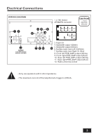
Electrical Connections WIRING DIAGRAM CAUTION +12V DC NEGATIVE GROUND 15A 15A 15 8. Front left PRE-AMP output (White) 9. Front right PRE-AMP output (Red) 10. Rear left PRE-AMP output (White) 11. Rear right PRE-AMP output (Red) 12. Radio antenna socket - Only use speakers with 4 ohm impedance. - The maximum current of the Amp Remote trigger is 200mA. 3
-
 1
1 -
 2
2 -
 3
3 -
 4
4 -
 5
5 -
 6
6 -
 7
7 -
 8
8 -
 9
9 -
 10
10 -
 11
11 -
12
-
13
-
14
-
15
-
16
 |
 |
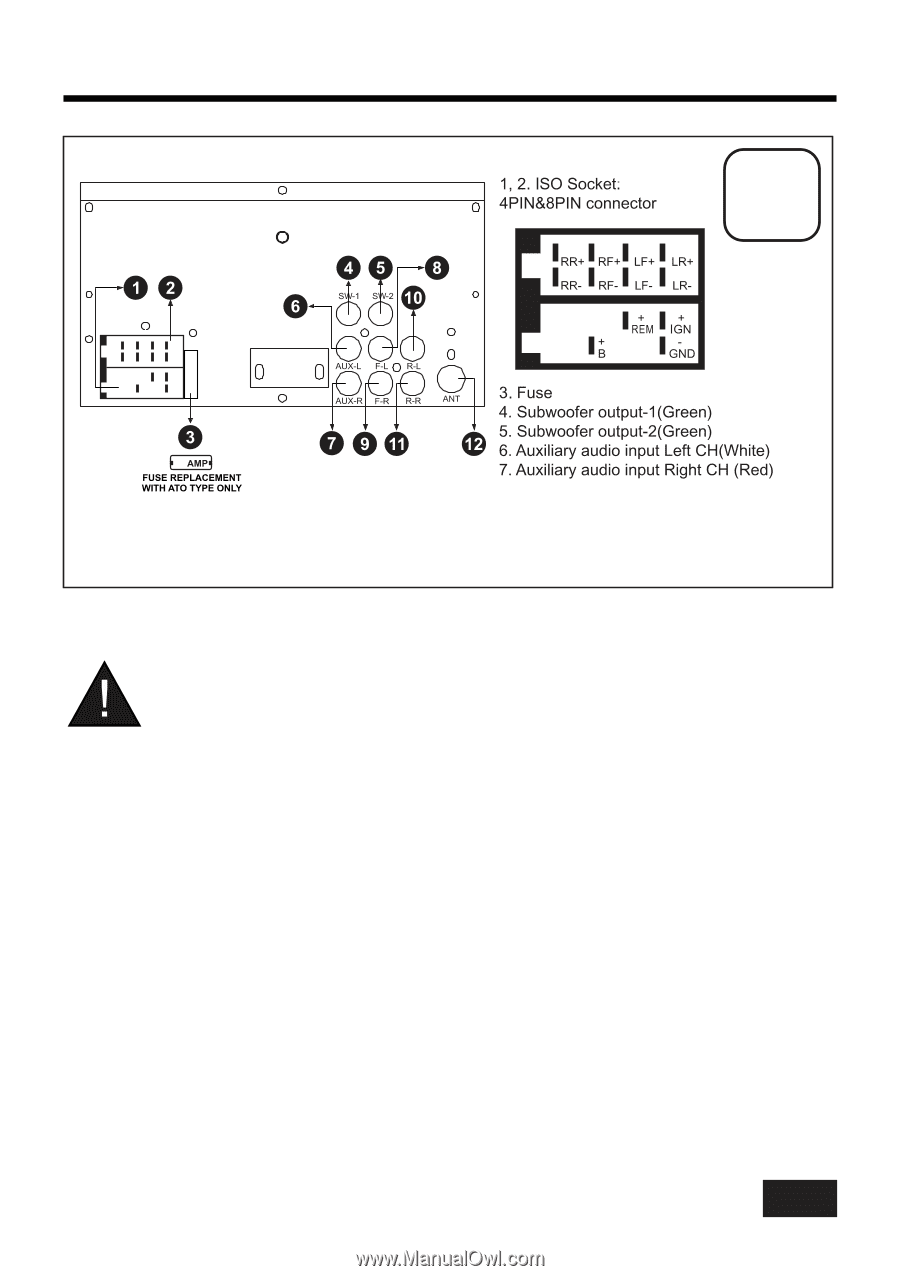
Electrical Connections
- Only use speakers with 4 ohm impedance.
-The maximum current of theAmp Remote trigger is 200mA.
WIRING DIAGRAM
CAUTION
+12V DC
NEGATIVE
GROUND
3
15A
15A
8. Front left PRE-AMPoutput (White)
9. Front right PRE-AMP output (Red)
10. Rear left PRE-AMPoutput (White)
11. Rear right PRE-AMPoutput (Red)
12. Radio antenna socket
15