Boss Audio CPBK2 User Manual in English - Page 4
apphcahon.18GA
 |
View all Boss Audio CPBK2 manuals
Add to My Manuals
Save this manual to your list of manuals |
Page 4 highlights
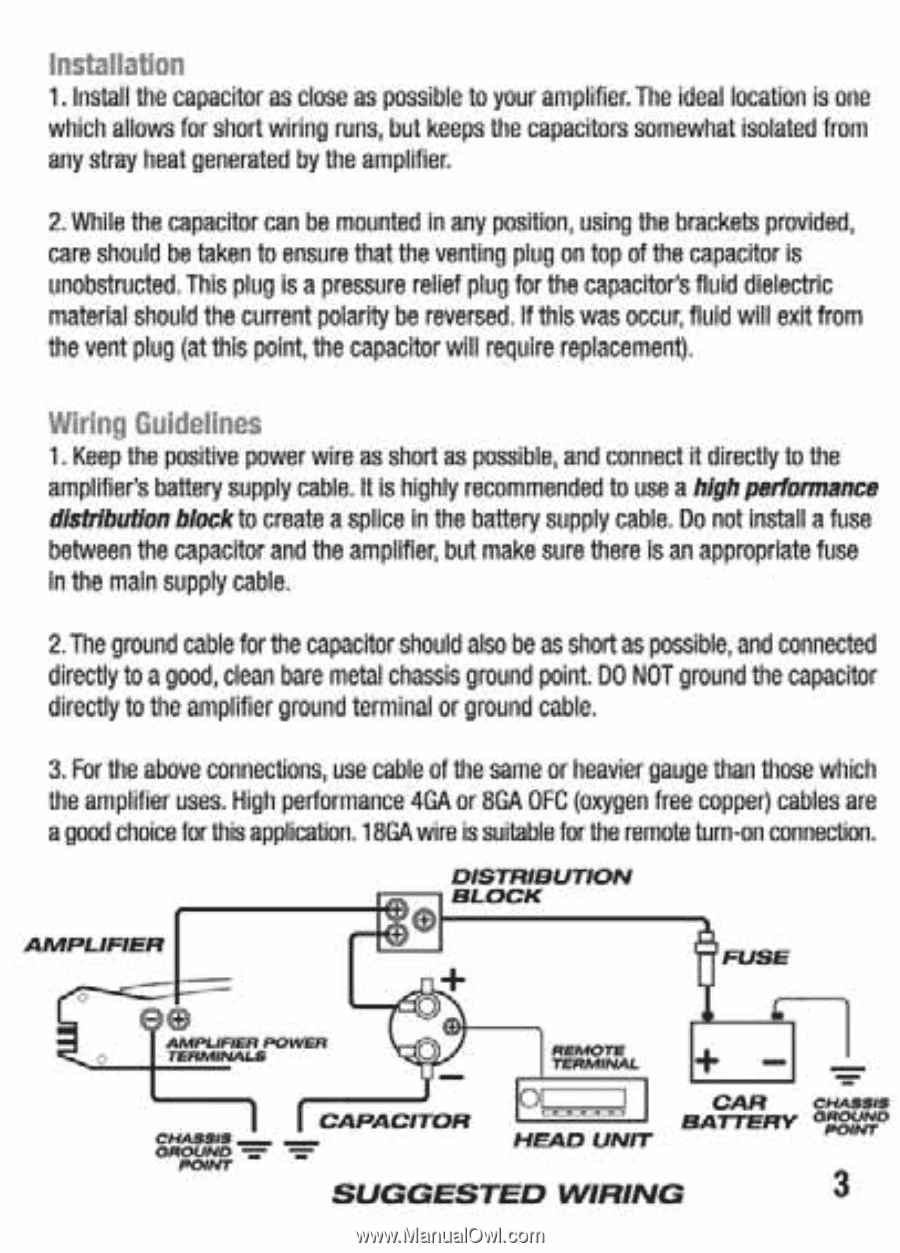
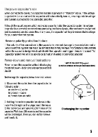
Installation 1. Install the capacitor as close as possible to your amplifier. The ideal location is one which allows for short wiring runs, but keeps the capacitors somewhat isolated horn any shay heal generated by the amplifier. 2. While the capacitor can be mounted In any position, using the brackets provided, care should be taken to ensure that the venting plug on top of the capacitor is unobstnicted This plug is a pressure relief plug for the capacitor's fluid dielectric material should the current polarity be reversed, if this was occur, fluid will exit from the vent plug (at this point, the capacitor will require replacement). Wiring Guidelines 1. Keep the positive power wire as short as possible, and connect it directly to the amplifier's battery supply cable. It is highly recommended to use a highperformance distribution block to create a splice In the battery supply cable. Do not install a fuse between the capacitor and the amplifier, but make sure there is an appropriate fuse In the main supply cable. 2. The ground cable for the capacitor should also be as short as possible. and connected directly to a good, dean bare metal chassis ground point. DO NOT ground the capacitor directly to the amplifier ground terminal or ground cable. 3. For the above connections, use cable of the same or heavier gauge than those which the ampiffle' uses. High pedormance 4GA or 8GA OFC (oxygen free copped cables are a good dioice lor this apphcahon.18GA wires suitable fix the remote turn•on connection. AMPLIFIER DISTRIBUTION • BLOCK AAalfiL/IPOINUI FIMINALS CHASSIS OPIOUPEO CAPACITOR CAR Chun. BATTERY affiX.N° MEAD UNIT SUGGESTED WIRING 3
-
 1
1 -
 2
2 -
 3
3 -
 4
4 -
 5
5 -
 6
6 -
 7
7
 |
 |