Boss Audio PH1500M User Manual in English - Page 13
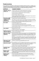
position. Insert high pass filter capacitors and a low pass filter inductor into
 |
View all Boss Audio PH1500M manuals
Add to My Manuals
Save this manual to your list of manuals |
Page 13 highlights
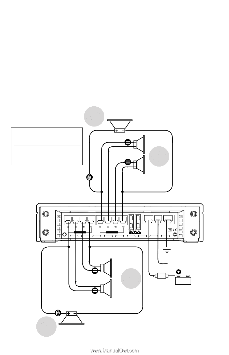
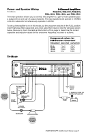
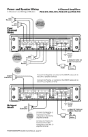
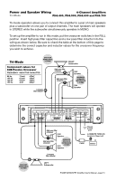
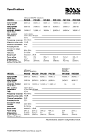
Power and Speaker Wiring 4-Channel Amplifiers Tri-Mode PH4.400, PH4.500, PH4.600 and PH4.700 Tri-mode operation allows you to connect this amplifier to a pair of main speakers plus a subwoofer on one pair of output channels. The main speakers will operate in STEREO while the subwoofer simultaneously operates in MONO. To set up the amplifier to run in this mode, put the crossover switches in the FULL position. Insert high pass filter capacitors and a low pass filter inductor into the wiring as shown below. Be sure to check the table at the bottom of this page to determine the correct capacitor and inductor values for the crossover frequency you wish to achieve. Tri-Mode SPEAKER IMPEDANCE 8 OHMS Component values for 6dB Passive Crossover FREQUENCY INDUCTOR CAPACITOR 80 Hz 100 Hz 120 Hz 150 Hz 7.5mH 6.5mH 5.5mH 4mH 470uF 330uF 330uF 220uF Low pass filter inductor RIGHT Subwoofer High pass filter crossover High pass filter crossover CH3 Speaker MINIMUM SPEAKER IMPEDANCE 4 OHMS CH4 Speaker SPEAKER IMPEDANCE 8 OHMS CH1 CH2 SPEAKER CONNECTIONS BRIDGED MODE CH3 CH4 SPEAKER CONNECTIONS BRIDGED MODE +12V GND FUSES REMOTE POWER CONNECTIONS High pass filter crossover - CH2 Speaker + MINIMUM High pass filter crossover SPEAKER IMPEDANCE - 4 OHMS CH1 + Speaker Low pass filter inductor LEFT Subwoofer Chassis ground point to REMOTE TURN-ON terminal of head unit FUSE Battery PHANTOM MOSFET Amplifier User's Manual - page 13
-
 1
1 -
2
-
3
-
4
-
5
-
6
-
7
-
 8
8 -
 9
9 -
 10
10 -
 11
11 -
 12
12 -
 13
13 -
 14
14 -
 15
15 -
 16
16
 |
 |