Brother International BAS-611 Instruction Manual - English - Page 39
Standard, Adjustments, Machine
 |
View all Brother International BAS-611 manuals
Add to My Manuals
Save this manual to your list of manuals |
Page 39 highlights
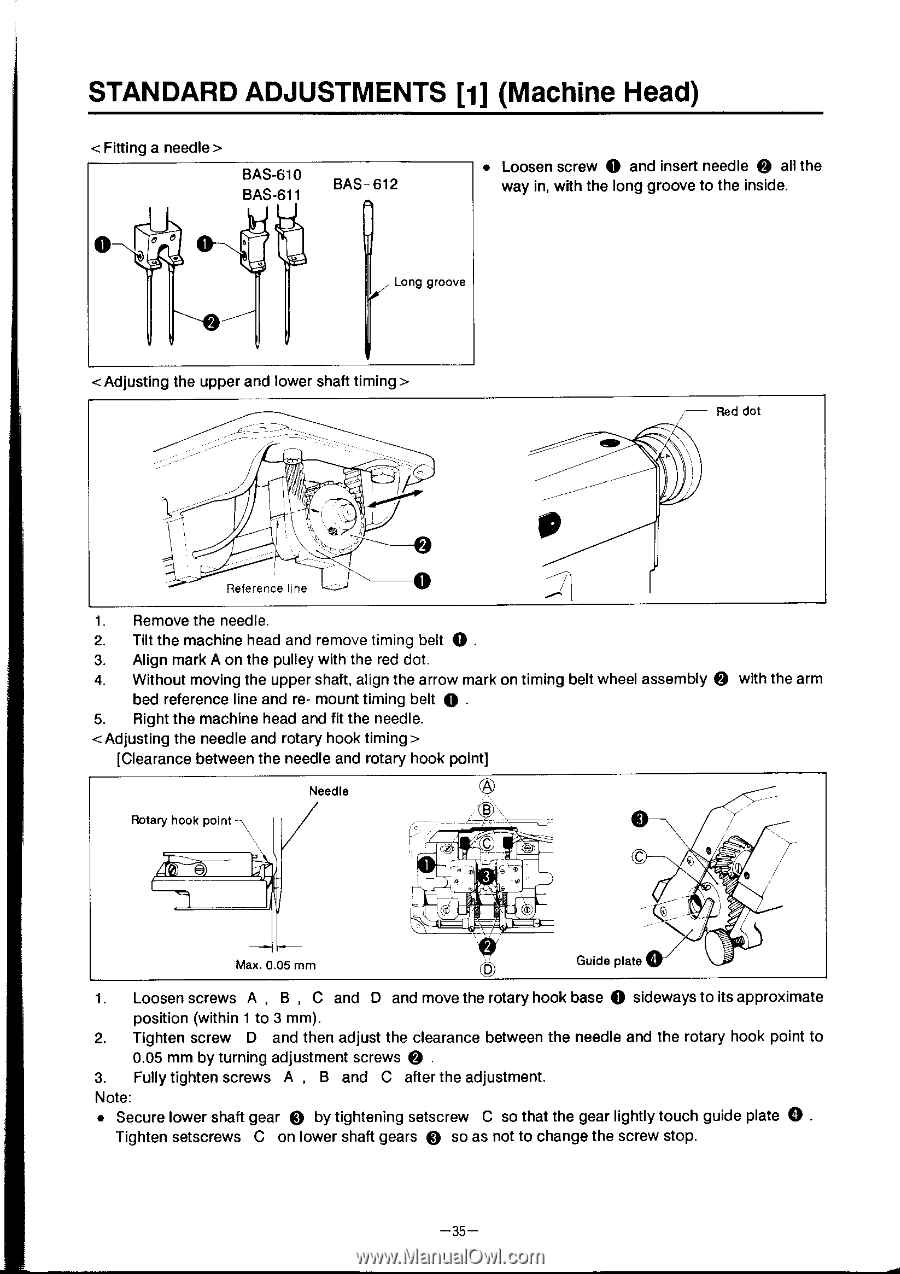
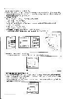
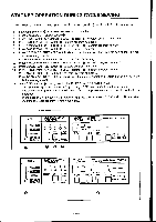
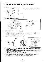
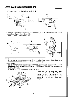
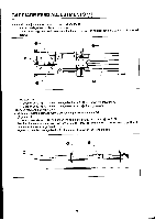
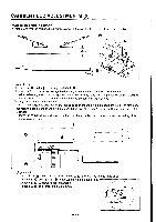
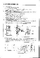
STANDARD ADJUSTMENTS [1] (Machine Head) < Fitting a needle > BAS-610 BAS-611 BAS- 612 • Loosen screw 0 and insert needle Q all the way in, with the long groove to the inside. Long groove Red dot p. Reference line 1. Remove the needle. 2. Tilt the machine head and remove timing belt 0 . 3. Align mark A on the pulley with the red dot. 4. Without moving the upper shaft, align the arrow mark on timing belt wheel assembly 0 bed reference line and re- mount timing belt 0 . 5. Right the machine head and fit the needle. [Clearance between the needle and rotary hook point] with the arm Rotary hook point -\\ Needle 8 (rf Max. 0.05 mm Guide plate 0 1. Loosen screws A , B , C and D and move the rotary hook base 0 sideways to its approximate position (within 1 to 3 mm). 2. Tighten screw D and then adjust the clearance between the needle and the rotary hook point to 0.05 mm by turning adjustment screws 3. Fully tighten screws A , B and C after the adjustment. Note: • Secure lower shaft gear 0 by tightening setscrew C so that the gear lightly touch guide plate 0 . Tighten setscrews C on lower shaft gears 0 so as not to change the screw stop. -35-
-
 1
1 -
2
-
3
-
4
-
5
-
6
-
7
-
8
-
9
-
10
-
11
-
12
-
13
-
14
-
15
-
16
-
17
-
18
-
19
-
20
-
21
-
22
-
23
-
24
-
25
-
26
-
27
-
28
-
29
-
30
-
31
-
32
-
33
-
 34
34 -
 35
35 -
 36
36 -
 37
37 -
 38
38 -
 39
39 -
 40
40 -
 41
41 -
 42
42 -
 43
43 -
 44
44 -
45
-
46
-
47
-
48
-
49
-
50
-
51
-
52
-
53
-
54
-
55
-
56
-
57
-
58
 |
 |