Brother International DCP-1400 Service Manual - Page 66
sensor
 |
View all Brother International DCP-1400 manuals
Add to My Manuals
Save this manual to your list of manuals |
Page 66 highlights
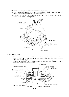
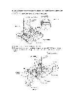
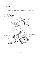
15) Remove the four screws and take off the flat cable clamp. Remove sponge 3 attached with adhesive tape. 16) Remove the CCD flat cable (which is attached with adhesive tape). Taptite, cup B M3x8 Flat cable clamp Arranging the CCD flat cable t CCD flat cable Sponge 3 Positioning rib O 325±2 CCD flat cable Scanner base 17) Remove the four screws and take off the guide plate. 18) Remove tape and sponges 1, then take out the panel harness and CCD HP sensor harness. NOTE: Once removed, the sponges 1 will become unusable and new ones will have to be put back in. Taptite, cup B M3x8 Guide plate Sponge 1 Tape CCD HP sensor harness Notch Sponge 1 0 Scanner base Notches Panel harness Panel harness IV - 22
-
 1
1 -
2
-
3
-
4
-
5
-
6
-
7
-
8
-
9
-
10
-
11
-
12
-
13
-
14
-
15
-
16
-
17
-
18
-
19
-
20
-
21
-
22
-
23
-
24
-
25
-
26
-
27
-
28
-
29
-
30
-
31
-
32
-
33
-
34
-
35
-
36
-
37
-
38
-
39
-
40
-
41
-
42
-
43
-
44
-
45
-
46
-
47
-
48
-
49
-
50
-
51
-
52
-
53
-
54
-
55
-
56
-
57
-
58
-
59
-
60
-
 61
61 -
 62
62 -
 63
63 -
 64
64 -
 65
65 -
 66
66 -
 67
67 -
 68
68 -
 69
69 -
 70
70 -
 71
71 -
72
-
73
-
74
-
75
-
76
-
77
-
78
-
79
-
80
-
81
-
82
-
83
-
84
-
85
-
86
-
87
-
88
-
89
-
90
-
91
-
92
-
93
-
94
-
95
-
96
-
97
-
98
-
99
-
100
-
101
-
102
-
103
-
104
-
105
-
106
-
107
-
108
-
109
-
110
-
111
-
112
-
113
-
114
-
115
-
116
-
117
-
118
-
119
-
120
-
121
-
122
-
123
-
124
-
125
-
126
-
127
-
128
-
129
-
130
-
131
-
132
-
133
-
134
-
135
-
136
-
137
-
138
-
139
-
140
-
141
-
142
-
143
-
144
-
145
-
146
-
147
-
148
-
149
-
150
-
151
-
152
-
153
-
154
-
155
-
156
-
157
-
158
-
159
-
160
-
161
-
162
-
163
-
164
-
165
-
166
-
167
-
168
-
169
-
170
-
171
-
172
-
173
-
174
-
175
-
176
-
177
-
178
-
179
-
180
-
181
-
182
-
183
-
184
-
185
-
186
-
187
-
188
-
189
-
190
-
191
-
192
-
193
-
194
-
195
-
196
-
197
-
198
-
199
-
200
-
201
-
202
-
203
-
204
-
205
-
206
-
207
-
208
-
209
-
210
-
211
-
212
-
213
-
214
-
215
-
216
-
217
-
218
-
219
-
220
-
221
-
222
-
223
-
224
-
225
-
226
-
227
-
228
-
229
 |
 |

15)
Remove
the
four
screws
and
take
off
the
flat
cable
clamp.
Remove
sponge
3
attached
with
adhesive
tape.
16)
Remove
the
CCD
flat
cable
(which
is
attached
with
adhesive
tape).
Sponge
3
Taptite,
cup
B
M3x8
Flat
cable
clamp
Positioning
rib
Arranging
the
CCD
flat
cable
t
O
Scanner
base
325±2
CCD
flat
cable
CCD
flat
cable
17)
Remove
the
four
screws
and
take
off
the
guide
plate.
18)
Remove
tape
and
sponges
1,
then
take
out
the
panel
harness
and
CCD
HP
sensor
harness.
NOTE:
Once
removed,
the
sponges
1
will
become
unusable
and
new
ones
will
have
to
be
put
back
in.
Tape
CCD
HP
sensor
harness
Notch
Sponge
1
Guide
plate
Panel
harness
IV
-
22
Taptite,
cup
B
M3x8
Notches
Panel
harness
Sponge
1
0
Scanner
base