Brother International HS-5000 Service Manual - Page 70
frame, Taptite, panel
 |
UPC - 012502524298
View all Brother International HS-5000 manuals
Add to My Manuals
Save this manual to your list of manuals |
Page 70 highlights
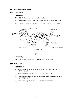
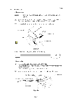
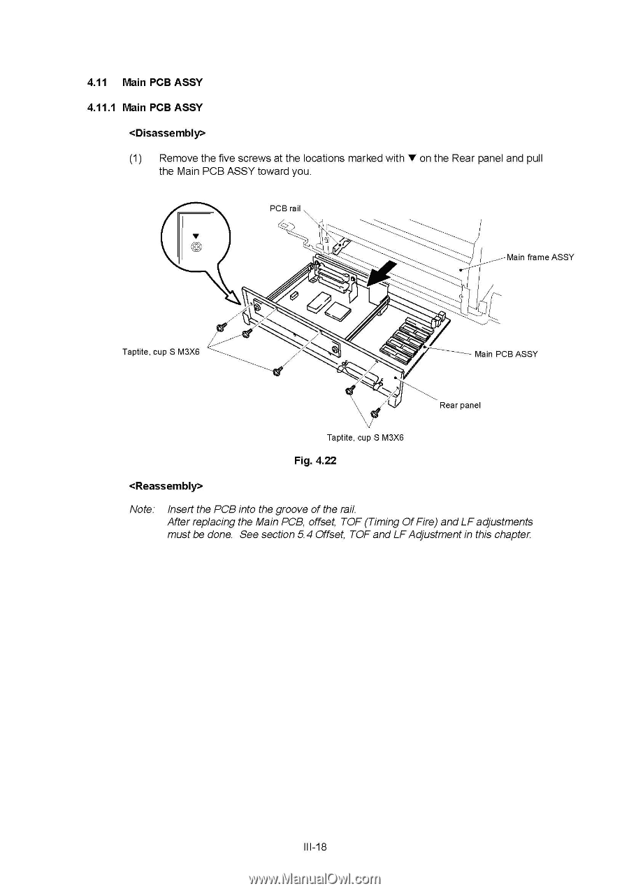
4.11 Main PCB ASSY 4.11.1 Main PCB ASSY (1) Remove the five screws at the locations marked with V on the Rear panel and pull the Main PCB ASSY toward you. PCB rail ti Main frame ASSY Taptite, cup S M3X6 Main PCB ASSY Rear panel Taptite, cup S M3X6 Fig. 4.22 Note: Insert the PCB into the groove of the rail. After replacing the Main PCB, offset, TOF (Timing OfFire) andLF adjustments must be done. See section 5.4 Offset, TOF and LF Adjustment in this chapter. III-18
-
 1
1 -
2
-
3
-
4
-
5
-
6
-
7
-
8
-
9
-
10
-
11
-
12
-
13
-
14
-
15
-
16
-
17
-
18
-
19
-
20
-
21
-
22
-
23
-
24
-
25
-
26
-
27
-
28
-
29
-
30
-
31
-
32
-
33
-
34
-
35
-
36
-
37
-
38
-
39
-
40
-
41
-
42
-
43
-
44
-
45
-
46
-
47
-
48
-
49
-
50
-
51
-
52
-
53
-
54
-
55
-
56
-
57
-
58
-
59
-
60
-
61
-
62
-
63
-
64
-
 65
65 -
 66
66 -
 67
67 -
 68
68 -
 69
69 -
 70
70 -
 71
71 -
 72
72 -
 73
73 -
 74
74 -
 75
75 -
76
-
77
-
78
-
79
-
80
-
81
-
82
-
83
-
84
-
85
-
86
-
87
-
88
-
89
-
90
-
91
-
92
-
93
-
94
-
95
-
96
-
97
-
98
-
99
-
100
-
101
-
102
-
103
-
104
-
105
-
106
-
107
-
108
-
109
-
110
-
111
-
112
-
113
-
114
-
115
-
116
-
117
-
118
-
119
-
120
-
121
-
122
-
123
-
124
-
125
-
126
-
127
-
128
-
129
-
130
-
131
-
132
-
133
-
134
-
135
-
136
-
137
-
138
-
139
-
140
-
141
-
142
-
143
-
144
-
145
-
146
-
147
-
148
-
149
-
150
-
151
-
152
-
153
-
154
-
155
-
156
-
157
-
158
-
159
-
160
-
161
-
162
-
163
-
164
-
165
-
166
-
167
-
168
 |
 |
4.11
Main
PCB
ASSY
4.11.1
Main
PCB
ASSY
<Disassembly>
(1)
Remove
the
five
screws
at
the
locations
marked
with
V
on
the
Rear
panel
and
pull
the
Main
PCB
ASSY
toward
you.
PCB
rail
ti
Main
frame
ASSY
Taptite,
cup
S
M3X6
Taptite,
cup
S
M3X6
Fig.
4.22
<Reassembly>
Main
PCB
ASSY
Rear
panel
Note:
Insert
the
PCB
into
the
groove
of
the
rail.
After
replacing
the
Main
PCB,
offset,
TOF
(Timing
Of
Fire)
and
LF
adjustments
must
be
done.
See
section
5.4
Offset,
TOF
and
LF
Adjustment
in
this
chapter.
III
-18