Brother International HS-5000 Service Manual - Page 75
connector.
 |
UPC - 012502524298
View all Brother International HS-5000 manuals
Add to My Manuals
Save this manual to your list of manuals |
Page 75 highlights
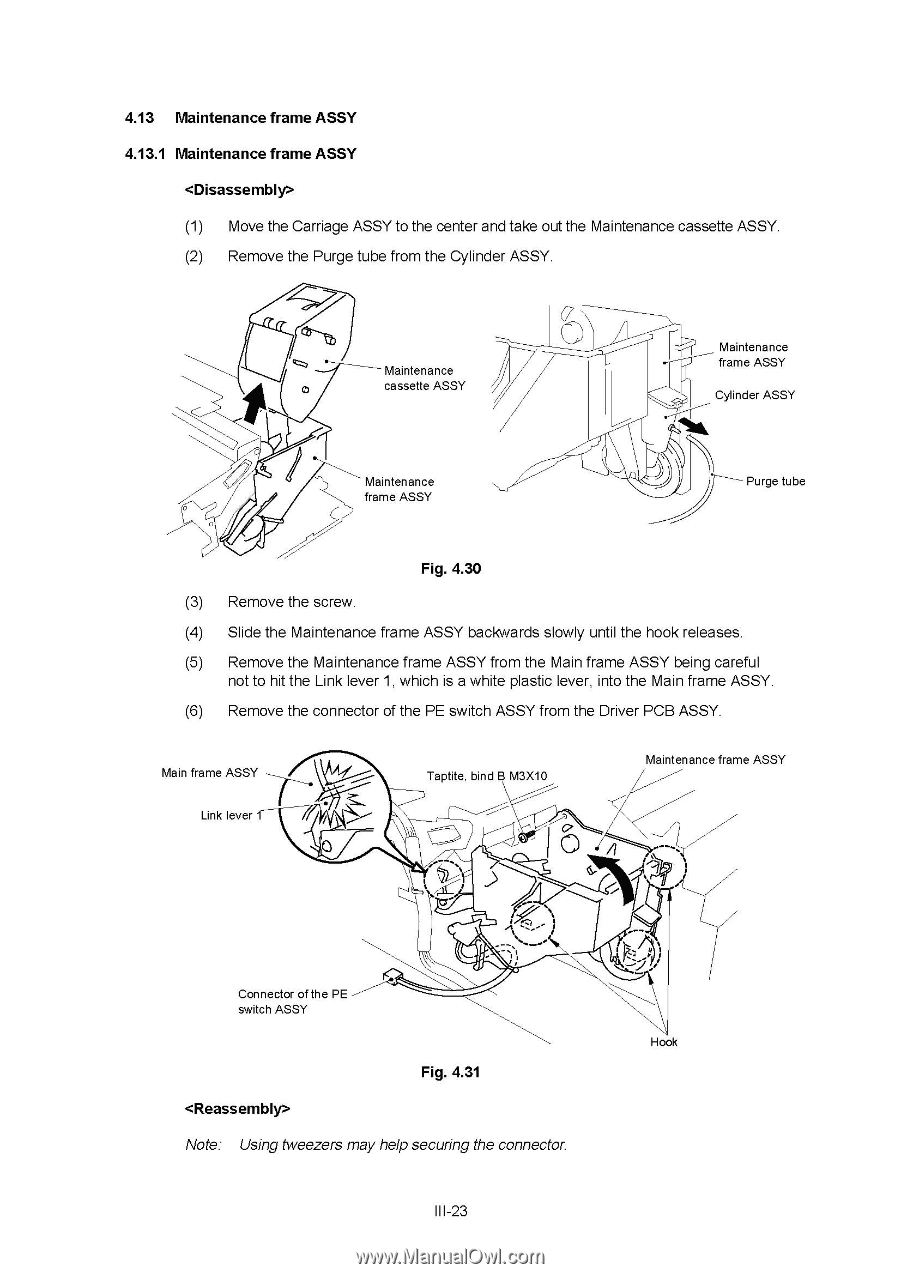
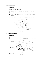
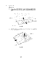
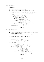
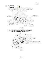
4.13 Maintenance frame ASSY 4.13.1 Maintenance frame ASSY (1) Move the Carriage ASSY to the center and take out the Maintenance cassette ASSY. (2) Remove the Purge tube from the Cylinder ASSY. Maintenance cassette ASSY Maintenance frame ASSY Cylinder ASSY 0 0 Maintenance frame ASSY Purge tube Fig. 4.30 (3) Remove the screw. (4) Slide the Maintenance frame ASSY backwards slowly until the hook releases. (5) Remove the Maintenance frame ASSY from the Main frame ASSY being careful not to hit the Link lever 1, which is a white plastic lever, into the Main frame ASSY. (6) Remove the connector of the PE switch ASSY from the Driver PCB ASSY. Main frame ASSY Link lever Taptite, bind B M3X10 Maintenance frame ASSY 4 I Connector of the PE switch ASSY Hook Fig. 4.31 Note: Using tweezers may help securing the connector. III-23
-
 1
1 -
2
-
3
-
4
-
5
-
6
-
7
-
8
-
9
-
10
-
11
-
12
-
13
-
14
-
15
-
16
-
17
-
18
-
19
-
20
-
21
-
22
-
23
-
24
-
25
-
26
-
27
-
28
-
29
-
30
-
31
-
32
-
33
-
34
-
35
-
36
-
37
-
38
-
39
-
40
-
41
-
42
-
43
-
44
-
45
-
46
-
47
-
48
-
49
-
50
-
51
-
52
-
53
-
54
-
55
-
56
-
57
-
58
-
59
-
60
-
61
-
62
-
63
-
64
-
65
-
66
-
67
-
68
-
69
-
 70
70 -
 71
71 -
 72
72 -
 73
73 -
 74
74 -
 75
75 -
 76
76 -
 77
77 -
 78
78 -
 79
79 -
 80
80 -
81
-
82
-
83
-
84
-
85
-
86
-
87
-
88
-
89
-
90
-
91
-
92
-
93
-
94
-
95
-
96
-
97
-
98
-
99
-
100
-
101
-
102
-
103
-
104
-
105
-
106
-
107
-
108
-
109
-
110
-
111
-
112
-
113
-
114
-
115
-
116
-
117
-
118
-
119
-
120
-
121
-
122
-
123
-
124
-
125
-
126
-
127
-
128
-
129
-
130
-
131
-
132
-
133
-
134
-
135
-
136
-
137
-
138
-
139
-
140
-
141
-
142
-
143
-
144
-
145
-
146
-
147
-
148
-
149
-
150
-
151
-
152
-
153
-
154
-
155
-
156
-
157
-
158
-
159
-
160
-
161
-
162
-
163
-
164
-
165
-
166
-
167
-
168
 |
 |