Brother International MD-817 Service Manual - Page 10
Configuration
 |
View all Brother International MD-817 manuals
Add to My Manuals
Save this manual to your list of manuals |
Page 10 highlights
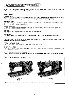
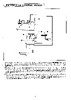
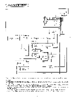
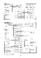
CONFIGURATION trd et& W o PLQ P Bea& Synchronizer 01/03mm Source DC. Servo motor Fuse Treadle Power supply Full-wave rectification -ass circuit Protective circuit Power transistor POWER CIRCUIT UNIT _.J Transformer r Power supply circuit 4, Power ON-OFF detection L 1 Motor drive circuit IPWM) Power supply cir uit Power ON-OFF detection Look protective circuit L_ Brake Operation panel CPU Speed detection Solenoid brake transistor CONTROL CIRCUIT UNIT Note: The sections enclosed by the broken line indicate where high voltage is applied. Handle these sections with great care. CAUTION: 1. When setting down the machine head or touching the needle, be sure to turn off the power switch and confirm that the pilot lamp is OFF. 2. Ground cables are provided for both single-phase and three-phase types; do not fail to ground the motor. (A ground cable is not provided for single-phase 110V types. Be sure to ground the motor frame if necessary.) 3. When adjusting the controls in the control box, be sure to turn off the power switch, remove the front cover and confirm that the pilot lamp is OFF. "It is dangerous to handle the control box when the power is on because high voltage is applied. Handle with great care. 4. Do not use the DC servomotor near machines which generate strong highe frequency electrical noise, e.g., arc welders.
-
 1
1 -
2
-
3
-
4
-
 5
5 -
 6
6 -
 7
7 -
 8
8 -
 9
9 -
 10
10 -
 11
11 -
 12
12 -
 13
13 -
 14
14 -
 15
15 -
16
-
17
-
18
-
19
-
20
-
21
-
22
-
23
-
24
-
25
-
26
-
27
-
28
-
29
-
30
-
31
-
32
-
33
-
34
-
35
-
36
-
37
-
38
-
39
-
40
-
41
-
42
-
43
-
44
-
45
-
46
-
47
-
48
-
49
-
50
-
51
-
52
-
53
-
54
-
55
-
56
-
57
-
58
-
59
-
60
-
61
-
62
-
63
-
64
-
65
-
66
-
67
-
68
-
69
-
70
-
71
-
72
-
73
-
74
-
75
-
76
-
77
-
78
-
79
-
80
-
81
-
82
-
83
-
84
-
85
-
86
-
87
-
88
-
89
-
90
-
91
-
92
-
93
-
94
-
95
-
96
-
97
-
98
-
99
-
100
-
101
-
102
-
103
-
104
-
105
-
106
-
107
-
108
-
109
-
110
-
111
-
112
 |
 |
