Brother International S-7200B Service Manual - Page 47
REPLACING PARTS, < Timing belt installation >, < Motor installation >
 |
View all Brother International S-7200B manuals
Add to My Manuals
Save this manual to your list of manuals |
Page 47 highlights
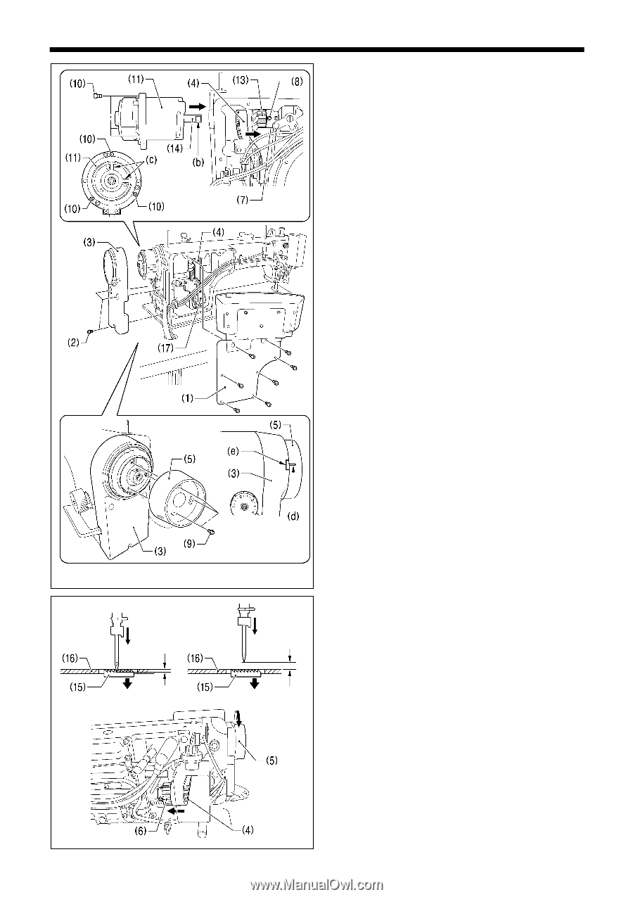
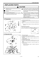
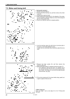
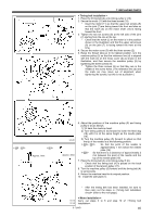
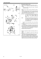
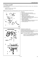
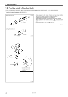
7. REPLACING PARTS < Timing belt installation > 1. Place the timing belt (4) onto timing pulley U (13). 2. Secure the motor (11) with the three screws (10). * Insert the motor (11) so that the upper set screws (8) on the joint (7) are facing toward the front and also so that the notch (b) on the motor shaft (14) is facing toward the front. 3. Tighten the two set screws (8) at the left side of the joint (7) starting from the one at the top. * Check that the notch (c) on the motor is in the position shown in the illustration and that the upper set screws (8) on the joint (7) is facing toward the front at this time. 4. Secure the motor cover (3) with the three screws (2). 5. Raise the thread take-up to its highest position, turn the machine pulley (5) so that the reference line (d) is aligned with the mark (e) on the motor cover (3) as shown in the illustration, and then secure the machine pulley (5) by tightening the three screws (9). * Tighten the three screws (9) so that they are in the middle of the screw holes. (The reference line (d) and the mark (e) may move out of alignment when tightening the screws, but this is not a problem.) Approx. 1mm 1212B Approx. 3mm 6. Adjust the positions of the machine pulley (5) and timing pulley D (6) as follows. 1) Tilt back the machine head. 2) Turn timing pulley D (6) forward to lower the feed dog (15) until it is at the same height as the needle plate (16). 3) Turn the machine pulley (5) forward to adjust so that the tip of the needle is at the following position. So that the point of the needle is approximately 1 mm below the needle plate (16) So that there is a clearance of approximately 3 mm between the point of the needle and the top of the needle plate (16) 7. Place the timing belt (4) onto timing pulley D (6). * Check that the timing belt (4) is placed on the back position of the tension pulley (17). 8. Turn the machine pulley (5) forward until the timing belt (4) is set securely. 9. Return the machine head to its original position. 10. Install the side plate (1). * After the timing belt has been installed, be sure to then carry out the steps in (refer to the next page). 1213B 1214B < Motor installation > Carry out steps 2 to 5 and step 10 of . S-7200B 40
-
 1
1 -
2
-
3
-
4
-
5
-
6
-
7
-
8
-
9
-
10
-
11
-
12
-
13
-
14
-
15
-
16
-
17
-
18
-
19
-
20
-
21
-
22
-
23
-
24
-
25
-
26
-
27
-
28
-
29
-
30
-
31
-
32
-
33
-
34
-
35
-
36
-
37
-
38
-
39
-
40
-
41
-
 42
42 -
 43
43 -
 44
44 -
 45
45 -
 46
46 -
 47
47 -
 48
48 -
 49
49 -
 50
50 -
 51
51 -
 52
52 -
53
-
54
-
55
-
56
-
57
-
58
-
59
-
60
-
61
-
62
-
63
-
64
-
65
-
66
-
67
-
68
-
69
-
70
-
71
-
72
-
73
-
74
-
75
-
76
-
77
-
78
-
79
-
80
-
81
-
82
-
83
-
84
 |
 |