Brother International XM2701 Operation Manual - Page 6
The Main Parts
 |
View all Brother International XM2701 manuals
Add to My Manuals
Save this manual to your list of manuals |
Page 6 highlights
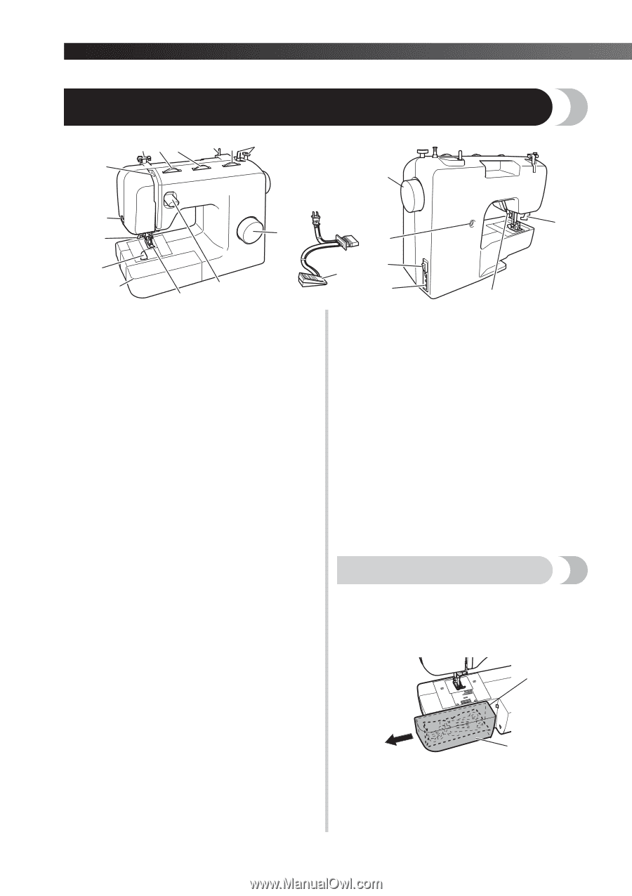
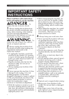
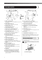
KNOWING YOUR SEWING MACHINE THE MAIN PARTS 654 3 2 1 7 E 8 9 D 0 A C B 1 Bobbin winder (Page 15) This winds the thread onto the bobbin for use as the lower thread. 2 Stitch length dial (Page 14) Rotate the dial to control the stitch length. 3 Spool pin (Page 15, 19) This holds the spool of thread. 4 Stitch width dial (Page 14) Rotate the dial to control the stitch width. 5 Upper tension-control dial (Page 29) This controls the tension of the upper thread. 6 Thread guide (Page 15, 19) This is used when winding the thread onto the bobbin and then threading the machine. 7 Thread take-up lever (Page 20) 8 Thread cutter (Page 26) Pass the threads through the thread cutter to cut them. 9 Needle threader (Page 21) (This is only available on certain models.) 0 Quick-set bobbin (Page 18) (This is only available on certain models.) A Flat bed attachment with accessory compartment (Page 5) B Presser foot (Page 8) C Reverse sewing lever (Page 14) Push this lever to stitch in the reverse direction. D Pattern selection dial (Page 9) Rotate the dial in either direction to choose the stitch you want. E Handwheel Used to manually raise and lower the needle. F Buttonhole fine-adjustment screw (Page 38) G Main power and sewing light switch (Page 7) You can turn the main power and sewing light switch on and off. J F KG H I H Foot controller jack / socket (Page 6) Plug in the foot controller plug and connect the machine to the power supply. I Presser foot lever (Page 19) Used to raise and lower the presser foot. J Buttonhole lever (1-Step automatic buttonhole) (Page 36) Lower the buttonhole lever when sewing buttonholes. K Foot controller (Page 7) You can use this to control the sewing speed, and to start and stop sewing. Foot Controller: Model KD-1902 for 110-120V area KD-1902 for 110-127V area (Brazil only) Model KD-2902 for 220-240V area The foot controller part code differs depending on the country or region. Contact your dealer or the nearest authorized service center. Flat bed attachment The accessories can be stored in a compartment inside the flat bed attachment. Slide the flat bed attachment to the left to 1 open it. 1 2 1 Flat bed attachment 2 Storage compartment 5
-
 1
1 -
 2
2 -
 3
3 -
 4
4 -
 5
5 -
 6
6 -
 7
7 -
 8
8 -
 9
9 -
 10
10 -
 11
11 -
 12
12 -
13
-
14
-
15
-
16
-
17
-
18
-
19
-
20
-
21
-
22
-
23
-
24
-
25
-
26
-
27
-
28
-
29
-
30
-
31
-
32
-
33
-
34
-
35
-
36
-
37
-
38
-
39
-
40
-
41
-
42
-
43
-
44
-
45
-
46
-
47
-
48
-
49
-
50
-
51
-
52
-
53
-
54
-
55
-
56
-
57
-
58
-
59
-
60
-
61
-
62
-
63
-
64
-
65
-
66
-
67
-
68
-
69
-
70
-
71
-
72
-
73
-
74
-
75
-
76
-
77
-
78
-
79
-
80
-
81
-
82
-
83
-
84
-
85
-
86
-
87
-
88
-
89
-
90
-
91
-
92
-
93
-
94
-
95
-
96
-
97
-
98
-
99
-
100
-
101
-
102
-
103
-
104
-
105
-
106
-
107
-
108
 |
 |