Campbell Scientific CR10X CR10X Measurement and Control System - Page 87
Differential Voltage, Measurement
 |
View all Campbell Scientific CR10X manuals
Add to My Manuals
Save this manual to your list of manuals |
Page 87 highlights
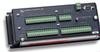
SECTION 7. MEASUREMENT PROGRAMMING EXAMPLES 7.2 DIFFERENTIAL VOLTAGE MEASUREMENT Some sensors either contain or require active signal conditioning circuitry to provide an easily measured analog voltage output. Generally, the output is referenced to the sensor ground. The associated current drain usually requires a power source external to the CR10X. A typical connection scheme where AC power is not available and both the CR10X and sensor are powered by an external battery is shown in Figure 7.2-1. Since a single-ended measurement is referenced to the CR10X ground, any voltage difference between the sensor ground and CR10X ground becomes a measurement error. A differential measurement avoids this error by measuring the signal between the 2 leads without reference to ground. This example analyzes the potential error on a differential CO2 measurement using a LI-COR CO2/H2O analyzer, model LI-6262. The wire used to supply power from the external battery is 18 AWG with an average resistance of 6.5 ohms/1000 ft. The power leads to the CR10X and LI-6262 are 2 ft and 10 ft, respectively. Typical current drain for the LI-6262 is 1000 mA. When making measurements, the CR10X draws about 35 mA. Since voltage is equal to current multiplied by resistance (V=IR), ground voltages at the LI-6262 and the CR10X relative to battery ground are: LI-6262 ground = 1A ∗ 6.5 ohms/1000 ft ∗ 10 ft = +0.065 V CR10X ground = 0.035A ∗ 6.5 ohms/1000 ft ∗ 2 ft = +0.0005 V Ground at the LI-6262 is 0.065 V higher than ground at the CR10X. The LI-6262 can be programmed to output a linear voltage (0 to 100 mV) that is proportional to differential CO2, 100 µmol/mol full scale, or 1 µmol/mol/mV. If the output is measured with a single-ended voltage measurement, it is 0.065 V or 65 µmol/mol high. If this offset remained constant, it could be corrected in programming. However, it is better to use a differential voltage measurement which does not rely on the current drain remaining constant. The program that follows illustrates the use of Instruction 2 to make the measurement. A multiplier of 1 is used to convert the millivolt output into µmol/mol. PROGRAM 01: Volt (Diff) (P2) 1: 1 Reps 2: 25 ±2500 mV 60 Hz Rejection Range 3: 1 DIFF Channel 4: 1 Loc [ umol_mol ] 5: 1 Mult 6: 0 Offset DIFF SE SE DIFF AG H L AG H L AG H L AG E3 AG G 748 9 5 10 11 6 12 CAMPBELL SCIENTIFIC INCCLTR.#1304T3C4R03 11 2 324 5 36 AG H L AG H L AG H L AG E1 E2 G G G G G G 12V 12V G 12V SERIAL I/O SWITCHED 12V POWER IN CR10 EARTH SWITCHED 12V CONTROL MADE IN USA WIRING PANEL NO. G G 5V 5V P1 P2 C8 C7 C6 C5 C4 C3 C2 C1 FIGURE 7.3-1. CR10TCR Mounted on the CR10X Wiring Panel 7-3
-
 1
1 -
2
-
3
-
4
-
5
-
6
-
7
-
8
-
9
-
10
-
11
-
12
-
13
-
14
-
15
-
16
-
17
-
18
-
19
-
20
-
21
-
22
-
23
-
24
-
25
-
26
-
27
-
28
-
29
-
30
-
31
-
32
-
33
-
34
-
35
-
36
-
37
-
38
-
39
-
40
-
41
-
42
-
43
-
44
-
45
-
46
-
47
-
48
-
49
-
50
-
51
-
52
-
53
-
54
-
55
-
56
-
57
-
58
-
59
-
60
-
61
-
62
-
63
-
64
-
65
-
66
-
67
-
68
-
69
-
70
-
71
-
72
-
73
-
74
-
75
-
76
-
77
-
78
-
79
-
80
-
81
-
 82
82 -
 83
83 -
 84
84 -
 85
85 -
 86
86 -
 87
87 -
 88
88 -
 89
89 -
 90
90 -
 91
91 -
 92
92 -
93
-
94
-
95
-
96
-
97
-
98
-
99
-
100
-
101
-
102
-
103
-
104
-
105
-
106
-
107
-
108
-
109
-
110
-
111
-
112
-
113
-
114
-
115
-
116
-
117
-
118
-
119
-
120
-
121
-
122
-
123
-
124
-
125
-
126
-
127
-
128
-
129
-
130
-
131
-
132
-
133
-
134
-
135
-
136
-
137
-
138
-
139
-
140
-
141
-
142
-
143
-
144
-
145
-
146
-
147
-
148
-
149
-
150
-
151
-
152
-
153
-
154
-
155
-
156
-
157
-
158
-
159
-
160
-
161
-
162
-
163
-
164
-
165
-
166
-
167
-
168
-
169
-
170
-
171
-
172
-
173
-
174
-
175
-
176
-
177
-
178
-
179
-
180
-
181
-
182
-
183
-
184
-
185
-
186
-
187
-
188
-
189
-
190
-
191
-
192
-
193
-
194
-
195
-
196
-
197
-
198
-
199
-
200
-
201
-
202
-
203
-
204
-
205
-
206
-
207
-
208
-
209
-
210
-
211
-
212
-
213
-
214
-
215
-
216
-
217
-
218
-
219
-
220
-
221
-
222
-
223
-
224
-
225
-
226
-
227
-
228
-
229
-
230
-
231
-
232
-
233
-
234
-
235
-
236
-
237
-
238
-
239
-
240
-
241
-
242
-
243
-
244
-
245
-
246
-
247
-
248
-
249
-
250
-
251
-
252
-
253
-
254
-
255
-
256
-
257
-
258
-
259
-
260
-
261
-
262
-
263
-
264
-
265
-
266
-
267
-
268
-
269
-
270
-
271
-
272
-
273
-
274
-
275
-
276
-
277
-
278
-
279
-
280
-
281
-
282
-
283
-
284
-
285
-
286
-
287
-
288
-
289
-
290
-
291
-
292
-
293
-
294
-
295
-
296
-
297
-
298
-
299
-
300
-
301
-
302
-
303
-
304
-
305
-
306
-
307
-
308
-
309
-
310
-
311
-
312
-
313
-
314
-
315
-
316
-
317
-
318
-
319
-
320
-
321
-
322
-
323
-
324
-
325
-
326
-
327
-
328
-
329
-
330
-
331
-
332
-
333
-
334
-
335
-
336
-
337
-
338
-
339
-
340
-
341
-
342
-
343
-
344
-
345
-
346
-
347
-
348
-
349
-
350
-
351
-
352
-
353
-
354
-
355
-
356
-
357
-
358
-
359
-
360
-
361
-
362
 |
 |
