Campbell Scientific LI200X LI200X-L LI-COR Silicon Pyranometer - Page 8
Wiring
 |
View all Campbell Scientific LI200X manuals
Add to My Manuals
Save this manual to your list of manuals |
Page 8 highlights
LI200X Pyranometer 3. Wiring FIGURE 2-3. 025 Crossarm Stand and 019ALU Crossarm A schematic diagram of the LI200X is shown in Figure 3-1. Connections to Campbell Scientific dataloggers are given in Table 3-1. When Short Cut software is used to create the datalogger program, the sensor should be wired to the channels shown in the wiring diagram created by Short Cut. TABLE 3-1. Connections to Campbell Scientific Dataloggers Color Red Black White Clear Description Signal Signal Reference Signal Ground Shield CR9000(X) CR5000 CR3000 CR1000 CR800 CR850 Differential High Differential Low CR510 CR500 CR10(X) Differential High Differential Low AG G 21X CR7 CR23X Differential High Differential Low 4
-
 1
1 -
2
-
 3
3 -
 4
4 -
 5
5 -
 6
6 -
 7
7 -
 8
8 -
 9
9 -
 10
10 -
 11
11 -
 12
12 -
 13
13 -
14
-
15
-
16
-
17
-
18
 |
 |

LI200X Pyranometer
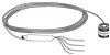
FIGURE 2-3.
025 Crossarm Stand and 019ALU Crossarm
3.
Wiring
A schematic diagram of the LI200X is shown in Figure 3-1.
Connections to Campbell Scientific dataloggers are given in Table 3-1.
When
Short Cut software is used to create the datalogger program, the sensor should
be wired to the channels shown in the wiring diagram created by Short Cut.
TABLE 3-1.
Connections to Campbell Scientific Dataloggers
Color
Description
CR9000(X)
CR5000
CR3000
CR1000
CR800
CR850
CR510
CR500
CR10(X)
21X
CR7
CR23X
Red
Signal
Differential
High
Differential
High
Differential
High
Black
Signal
Reference
Differential
Low
Differential
Low
Differential
Low
White
Signal Ground
AG
Clear
Shield
G
4