Campbell Scientific SDM SDM-SW8A 8-Channel Switch Closure Input Module - Page 8
Connections, Internal Jumpers
 |
View all Campbell Scientific SDM manuals
Add to My Manuals
Save this manual to your list of manuals |
Page 8 highlights
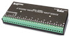
SDM-SW8A Switch Closure Input Module 4. Connections All connections to the datalogger, power supply, and other SW8As are made from terminals located under "TO DATALOGGER" on the SW8A (refer to Figure 1). Sensor connections are made at the remaining terminals. 4.1 Connections to Dataloggers and Other SW8As The CABLE5CBL or a similar cable is used to connect the SDM-SW8A to a datalogger. Connections between an SW8A and a datalogger are shown in Table 1. Connections to multiple SW8As are shown in Table 2. CAUTION 1. The order in which connections are made is critical. ALWAYS CONNECT GROUND FIRST, followed by 12 V and then the Control Ports. 2. The sum of all the cable lengths connecting SW8As or other SDM devices and a datalogger should be as short as possible and preferably does not exceed 20 ft. Longer lead lengths may be possible for CRBasic dataloggers if the SDMSpeed instruction is used (see Section 6.1.2). Long lead lengths may prevent communication. 4.2 Sensor Connections Figure 2 shows the connections between the SW8A and compatible sensor types. 5. Internal Jumpers Inside the SW8A, jumpers must be set to configure the Module address and the channel measurement type for each channel. Remove the two panel screws and lift the cover to access the jumpers. Figure 2 shows jumper location. 5.1 Address Jumpers Each module can have 1 of 16 addresses (00 to 33, Base 4). The address is factory set to 00. Figure 2 shows the location of the address jumper block. Table 3 lists the jumper settings for each address. 4
-
 1
1 -
2
-
 3
3 -
 4
4 -
 5
5 -
 6
6 -
 7
7 -
 8
8 -
 9
9 -
 10
10 -
 11
11 -
 12
12 -
 13
13 -
14
-
15
-
16
-
17
-
18
-
19
-
20
-
21
-
22
-
23
-
24
-
25
-
26
-
27
-
28
 |
 |
