Carvin C1644 Instruction Manual - Page 4
Master
 |
View all Carvin C1644 manuals
Add to My Manuals
Save this manual to your list of manuals |
Page 4 highlights
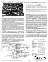
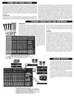
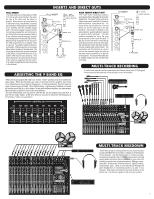
MASTER SECTION 15. CHANNEL MUTE SWITCH 20. TWO STEREO 24-BIT EFFECTS Use the MUTE switch to kill the channel. This feature saves The internal 24-BIT stereo processors receive signals from having to reset your faders and monitor sends. the EFF 1 / EFF 2 channel controls. If the adjacent PK (peak) 16. CHANNEL PFL SWITCH This switch allows the operator to listen to a channel (pre fader listen) in the headphone mix to set tone and gain levels as well as see the channel at the LED meter output (#32). 17. CHANNEL ASSIGNMENT SWITCHES These switches assign the channels' signal to the Master L/R faders, or to the SUB-GROUP faders 1 & 2, 3 & 4 for submixing in stereo pairs. For mono, PAN fully to the left and assign a channel to Sub-Group fader 1 or 3 only. PAN fully to the right and assign a channel to Sub-Group fader 2 or 4. Likewise assigning the L/R switches sends the channel directly to the main L or R faders. LED flashes, reduce the level from the channel EFF 1 / EFF 2 control. A "solid" PK LED will show EFFECTS 1 or 2 have been muted, either by the MUTE switches or by the optional FS22 footswitch (#41). The RETURN control will adjust the volume level of the selected effects. Remember each channel has its own EFFECT send that will send the signal to the effects processors. The red PK LED will indicate when the effects signal from the channel is distorting. Reduce the level of the channel EFFECT control until the PK LED stops flashing. EFFECT AND PARAMETERS ECHO: When the SELECT control is at the "7 O-clock" position, it is selected to the first ECHO setting where you get a single repeat echo (minimal regeneration). Turning the PARAMETER control to 1 will provide the short- 39 40 43 41 42 44 est delay time between the original signal and the echo. Increasing the 3 14 15 16 PHANTOM LINE LINE POWER 9-16 MIC MIC MIC 1 MON 1 GROUPS 2 MON 2 3 MON 3 EFF SW 1-2 PHONES L 4 MON 4 TAPE OUT L RR PARAMETER control to the right will increase the time delay between the original signal and the echo. To 45 increase the number of echo repeats, turn the SELECT control clockwise INSERT INSERT INSERT EFF 1 EFF 2 3L RETURN 3R TAPE IN MONO RTN 4 to "9 O-clock" (maximum regener46 ation). LO 0 CUT LO 0 50 CUT GAIN 0 LO 0 50 CUT GAIN 0 LO 0 50 CUT GAIN 0 HI HI HI HI - 15 + 15 - 15 + 15 - 15 + 15 1k 1k 1k 1k FREQ FREQ FREQ 0 0 0 100 5k 100 5k 100 5k 100 5k MID MID MID MID - 15 + 15 - 15 + 15 - 15 + 15 LOW 0 LOW 0 LOW 0 LOW - 15 + 15 - 15 + 15 - 15 + 15 MON 1 5 MON 1 5 MON 1 5 MON 1 0 MON 3 2/3 6 9 MON 3 0 10 3 OFF 3 MON 2/3 6 6 9 9 MON 2 MON 3 0 10 3 OFF 3 MON 2/3 6 6 9 9 MON 2 MON 3 0 10 3 OFF 3 MON 2/3 6 6 9 9 MON 2 MON 3 MON 4 ALT EFF 02 EFF 3 1/2 6 9 EFF 2 5 MON 4 ALT EFF 0 10 2 3 OFF 3 EFF 1/2 6 6 9 9 EFF 1 EFF 2 5 MON 4 ALT EFF 0 10 2 3 OFF 3 EFF 1/2 6 6 9 9 EFF 1 EFF 2 5 MON 4 ALT EFF 0 10 2 3 OFF 3 EFF 1/2 6 6 9 9 EFF 1 EFF 2 PAN C PAN C PAN C PAN R LR LR LR 14 15 16 SIG SIG SIG SIG AK PEAK PEAK PEAK MUTE +12 MUTE +12 MUTE +12 MUTE PFL +6 PFL +6 PFL +6 PFL 0 0 0 1-2 1-2 1-2 1-2 -6 -6 -6 3-4 3-4 3-4 3-4 -12 -12 -12 L-R -24 L-R -24 L-R -24 L-R -30 -30 -30 -50 -50 -50 3 14 15 16 +12 12+ POWER 8 4 8 4 EQ 1 EQ 2 0 0 4 4 8 8 LEFT / RIGHT / ±12 12- MON 1 MON 2 CONCERT SERIES C1644 +12 8 4 0 4 8 ±12 63 125 250 500 1K 2K 4K 12+ 8 4 0 4 8 12- 8K 16K 24-BIT DUAL STEREO EFFECTS EFFECTS 1 PK 4 5 6 3 7 2 8 3 OFF 3 6 6 MUTE 1 0 9 10 9 9 MON 1 MON 2 EFFECTS 2 PK 4 5 6 3 7 2 8 MUTE 1 0 9 10 3 OFF 3 6 6 9 9 MON 1 MON 3 56 4 7 3 8 2 9 1 10 56 4 7 3 8 2 9 1 10 SOURCE RETURN TO MONITORS SELECT PARAMETER EFF2 SELECT ECHO REVERB CHORUS FLANGE REGEN DAMPING REV LEVEL SPEED MON4 PARAM TIME DECAY DEPTH DEPTH PEAK +18 +12 +6 0 - 6 -12 -18 -24 -30 dB LR RETURN TAPE IN MONITORS 5 5 5 5 5 5 MONO 5 0 10 RTN 3 0 10 RTN 4 0 10 MON 1 0 10 MON 2 +12 LEFT 12 LEFT 12 LEFT 12 0 10 MON 3 LEFT RIGHT RIGHT RIGHT RIGHT +6 6 6 6 0 0 0 0 PFL PFL PFL PFL -6 -6 -6 -6 -12 -12 -12 -12 -24 -24 -24 -24 -30 -30 -30 -30 -50 -50 -50 -50 0 10 MON 4 +12 +6 0 -6 -12 -24 -30 -50 0 10 PFL PHONES 5 0 10 L-R MONO MON 1-2 MON 3-4 METERS 1 2 3 4 LR REVERB: When the SELECT control 38 37 is at the "10 O-clock" position, it is selected to the first REVERB setting. 36 Turning the SELECT control clock- 35 wise will increase the amount of high 33 frequencies in the reverb. Turning the PARAMETER control to 1 will pro- 33 vide minimal decay time of the reverb. Increasing to the right will increase the reverb decay time. CHORUS: When the SELECT con32 trol is at the "1 O-clock" position it is selected to the first CHORUS setting. Turning the SELECT control clockwise will increase the amount reverb in the chorus. Turning the 20 PARAMETER control to 1 will pro21 vide a minimal chorus depth setting. Increasing to the right will increase 24 the chorus depth. FLANGE: When the SELECT control 29 is at the "4 O-clock" position it is 31 selected to the first FLANGE setting. 27 Turning the SELECT control clock30 wise will increase the flanger's speed. Turning the PARAMETER control to 1 will provide minimal flanging depth. Increasing to the right will increase the flanger's depth. To send effects to the monitors, use the "TO MONITORS" controls, MON 1/MON 2 & MON 1/MON 3. The center position on both con- 22 23 25 26 28 trols is OFF. 18. CHANNEL FADER The CHANNEL FADER adjusts the output level of the channel. The signal will go to one or more of the Master Faders, depending on both the Channel Assignment switches and the PAN control. Calibrated 60mm FADERS with audio taper are featured for smooth fade-outs. Slide all faders down when connecting your inputs. Note: for best board performance, channel faders should be set slightly higher than the Sub-Groups and Master L/R faders. 21. SOURCE EFF2/MON4 SWITCH In the "OUT" position, the EFFECTS2processor gets its signal from the EFF2 channel send control. Clicking this switch "IN" will route the MON 4 mix (#10) to the internal EFFECTS 2 processor. This allows both effects to be used on each channel simultaneously. 22. RETURN 3 L/R Receives stereo or 2 mono effect signals from the RETURN 3 L /R jacks. These signals will also be present at MON 1 (#39). 19. MIC PHANTOM POWER SWITCH / RED LED This switch provides phantom power for condenser mics such as Carvin's CM90E in groups of 8 channels. This leaves the remaining MIC inputs for sources that don't require phantom power. The LINE inputs are unaffected by phantom power. 23. RCA TAPE IN/RTN EFF4 JACKS Receives a signal from the RTN 4 L/R 1/4" jacks (#38) & from the TAPE IN jacks (#44). These signals will also be present at MON 1. 24. MONITOR 1-4 CONTROLS These are the master outputs for the four monitor sends. These correspond to the balanced 1/4" MON 1-4 output jacks (#39). 25. GROUP/SUB-MIX FADERS 1-4 Once a channel has been assigned to one of these faders, the mixing process is simplified to using these four faders. If these faders are not assigned to the Master L-R faders (#27), then each fader is bused to the corresponding 4 GROUP 1/4" outputs (#40). By assigning the 4 faders to the Master L-R faders, the operator can use the faders to sub-mix groups. 26. GROUP PFL SWITCHES These PFL switches allow the operator to monitor the entire GROUP mix. If distortion is heard or if the PFL level is near PEAK on the Master L/R METERS, lower the channel faders assigned to that group. Also check the channel PEAK LEDs. 27. GROUP ASSIGNMENT SWITCHES These switches send the sub-group mix to the main L/R faders. For mono mixing, assign to both L/R. 28. MASTER L/R FADERS These faders adjust the level of the main stereo output created by all channels and groups assigned to L/R faders. Output appears at the L/R balanced XLR connectors (#45). 29. MONO OUTPUT The C44 SERIES creates an extra mono output from the L/R master faders (post) for center, side fill speakers or subwoofers. The output is at the MONO XLR connector (#46). 30. HEADPHONE AND METER SOURCE The stereo PHONES control sets the level of the PHONES jack (#42). The PFL, L/R, MONO, MON 1-2 and MON 3-4 switches allow for isolation of these sources through the headphones and the L/R LED METERS (#32). 31. PFL RED LED Indicates that the headphone & meters are monitoring only the channels or groups where the PFL is switched on. 32. L/R LED VU METERS This group of 10 LEDs offer 6 dB increment resolution that give the operator a visual indication of the mixer's output levels, selectable by the METER SOURCE or PFL switches (#30). 33. DUAL PRECISION 9 BAND GRAPHIC EQs are one octave filters at 60,125, 250, 500, 1k, 2k, 4k, 8k & 16k Hz centers that offer ±12dB adjustment to help eliminate feedback & enhance tone for the main or monitor mix. 34. EQ SWITCH 1 & 2 These switches swap the 9 band EQ's from the standard L/R main outputs "OUT" to the MON 1 & MON 2 outputs "IN" respectively. 35. POWER LED Verifies the mixer is on. 36. EFFECTS 1 & 2 OUTPUT JACKS 1/4" outputs drive external effects. Connect your effects processor's inputs to these jacks. 37. RETURN 3 L/R INPUT JACKS Returns a stereo signal from an external effect. Connect your effects processors' stereo outputs to these jacks. If only one RTN 3 jack is used, the mono signal will go to both L/R . 38. RTN 4 L/R INPUT JACKS Returns a stereo signal from other sources. 39. MONITOR 1-4 OUTPUT JACKS The C44 SERIES provides balanced 1/4" outputs for long cable runs. Connect your monitor power amps to these jacks. 40. GROUP 1-4 OUTPUT JACKS The C44 SERIES provides balanced 1/4" outputs. Connect your 4-track recorder or side fill power amps to these jacks. 41. EFF SW 1-2 FOOTSWITCH JACK The optional FS22 will remotely shut off EFFECTS 1 or 2. 42. HEADPHONE JACK 1/4" stereo jack for headphone or control room output. 43. RCA L & R TAPE OUT RCA jacks for connecting to a tape recorder input. 44. RCA L & R TAPE IN For stereo playback of a tape/CD (parallel with RTN 4 jacks). 45. L/ R XLR OUTPUT CONNECTORS This set of balanced XLR connectors are for connecting the main L/R output to power amps or recording gear. 46. MONO XLR OUTPUT CONNECTOR A balanced XLR output is featured for side fills or subwoofers. 3
-
 1
1 -
 2
2 -
 3
3 -
 4
4 -
 5
5 -
 6
6
 |
 |
