Carvin C2440 Instruction Manual - Page 4
L-r Sub To Center Switches
 |
View all Carvin C2440 manuals
Add to My Manuals
Save this manual to your list of manuals |
Page 4 highlights
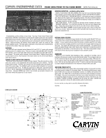
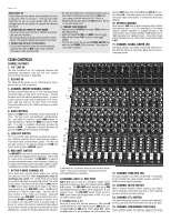
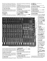
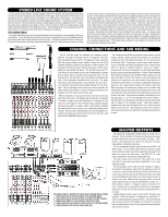
Master Section. Each channel can be assigned to the 12, 3-4, and L-R Faders in stereo pairs. This feature allows the operator to group certain channels (such as the channels used to mic an entire drum kit) and assign them to one pair of the master faders in the 1-2, 3-4 sub group. This sub-mixing feature decreases the number of channel faders that need to be adjusted. 16. AUDIO TAPER FADERS Slide all faders down when connecting your inputs. Increase each channels fader to achieve the overall mix. Calibrated 60mm faders with audio taper are featured for smooth fade-outs. MASTER SECTION 17. GROUPS 1 - 4 Once a channel has been assigned to one of the 4 groups (see 15), 60mm faders control the level of each group. The 4 output connections (see 38) are the output of these 4 faders. By assigning the 4 faders to the L & R faders and/or the Center fader the operator can use the 4 groups as sub-mixes. Each fader has assignment switches and a sub-mix pan control for L-R assignments. 18. MASTER LEFT & RIGHT FADERS These faders send the main stereo mix from all channels and GROUPS assigned to the L-R Faders. This mix is then routed to the main balanced and unbalanced output connectors (see 37). The left and right signals will be identical if all pan controls are set to their center positions. 19. CENTER FADER The Center fader gets its signal only from the center assignment switches on the 4 groups and L-R. The Center channel is great for a third main mix, a subwoofer out or in the case of a main mono mix, group 1-4 and L-R creates a 6 buss console. 20. CONTROL ROOM SELECTION SWITCHES Use these switches to select what is heard through the headphones and control room jacks. Select LEFT-RIGHT, CENTER, GROUP 1-2 or GROUP 3-4 28. POWER LED Verifies the mixer is on. 29. PHONES JACK 1/4" stereo jack for headphone or control room output. 30. TAPE IN TO L-R SWITCH This switch assigns the source coming from the RCA TAPE IN connections to the L-R mix. 21. PFL RED LED Indicates that the headphone, control room, and meters are monitoring the channels where the PFL is switched on. 22. L-R SUB TO CENTER SWITCHES Assignes the LEFT-RIGHT mix to the CENTER Fader. 31. TAPE IN CONTROL This adjusts the level of the source coming from TAPE IN. 32. CONTROL ROOM JACK This 1/4" stereo connection is for headphones or connecting a control room power amp & studio reference monitors. 23. PHONES CONTROL The PHONES control sets the desired level of the PHONES jack for monitoring through headphones. 41 40 39 38 37 33. TAPE OUT SOURCE This switch changes the tape out source from L-R to AUX 3-4. This is a great feature for 2 track live recording where a different mix is needed from the L-R house mix 34. STEREO RETURNS Each return contains a mas- ter level for the L-R mix and a 37 master level for the AUX (monitor mix) with RETURN 1 & 2 going to AUX 1, and 3 & 4 going to AUX 2. 36 35 35. TAPE IN-OUT 34 Stereo RCA jacks for con33 necting a tape recorder or CD 32 player. 31 36. CENTER 30 XLR balanced output from 29 28 the CENTER fader. 27 37. LEFT / RIGHT XLR & 1/4" CONNECTORS 26 This set of balanced and unbalanced connectors are 25 for connecting the main mix to external power amp(s). 24 38. 1/4" GROUP OUT- PUT CONNECTORS 23 1 through 4 offer output of 22 each individual GROUP fader 21 for use in multitrack recording or connecting additional power amps for stage monitors or main house speakers. 20 39. AUX SENDS Six 1/4" output connectors drive external effects. Or, use these sends to drive additional power amps for stage monitors. The C2440 provides balanced 1/4" outputs for long cable runs on AUX SENDS 1 & 2. 17 24. CONTROL ROOM The CONTROL ROOM knob adjusts the level of CONTROL ROOM output jack for monitoring. 25. L-R LED VU METERS This group of LEDs are ten segment 6 dB resolution meters that give the operator the mixer output from 30mv to 15.8vac. 26. AUX SENDS These are the Master Sends for AUX 1-6. Each has its own PFL switch to assist in adjusting the send level. 27. CONTROL ROOM LISTEN These 5 switches function just like the Control Room Selection Switches (see 20) providing a stereo listen for the 4 returns and Tape In. 18 19 40. AUX RETURNS Four 1/4" stereo pairs (8 inputs) to return external effects in stereo. 42. MIC PHANTOM POWER SWITCH / RED L E D This switch provides phantom power for condenser mics in groups of 8 channels. This allows other channel groups to remain non-powered to use the LINE inputs for instruments and MIC inputs for mics that don't require phantom power. The groups reduces noise and wasted power.
-
 1
1 -
 2
2 -
 3
3 -
 4
4 -
 5
5 -
 6
6
 |
 |
