Casio QT 6000 Service Manual - Page 12
Open The Card Slot Cover., Card Slot Cover
 |
View all Casio QT 6000 manuals
Add to My Manuals
Save this manual to your list of manuals |
Page 12 highlights
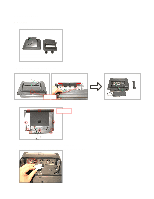
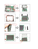
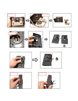
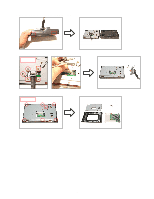
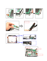
7. Open the CARD SLOT COVER. 8. Remove each screw, and then the PC CARD and the COVER for the CF CARD. CARD SLOT COVER Screws 9. Release the hook and remove the REAR CASE. Be careful with the REAR CASE when removing it since there is a wiring which connects to the speaker. 10. Remove the connector for the speaker. 11. Remove four screws and the iron plate. 12. Remove three screws. Screw × 4 Screw × 3 13. Remove four connectors, one FPC and the IO unit. FPC Connectors - 10 -
-
 1
1 -
2
-
3
-
4
-
5
-
6
-
 7
7 -
 8
8 -
 9
9 -
 10
10 -
 11
11 -
 12
12 -
 13
13 -
 14
14 -
 15
15 -
 16
16 -
 17
17 -
18
-
19
-
20
-
21
-
22
-
23
-
24
-
25
-
26
-
27
-
28
-
29
-
30
-
31
-
32
-
33
-
34
-
35
-
36
-
37
-
38
-
39
-
40
-
41
-
42
-
43
-
44
-
45
-
46
-
47
-
48
-
49
-
50
-
51
-
52
-
53
-
54
-
55
-
56
-
57
-
58
-
59
-
60
-
61
-
62
-
63
-
64
-
65
-
66
-
67
-
68
-
69
-
70
-
71
-
72
-
73
-
74
-
75
-
76
-
77
-
78
-
79
-
80
-
81
-
82
-
83
-
84
-
85
-
86
-
87
-
88
-
89
-
90
-
91
-
92
-
93
-
94
-
95
-
96
-
97
-
98
-
99
-
100
-
101
-
102
-
103
-
104
-
105
-
106
-
107
-
108
-
109
-
110
-
111
-
112
-
113
-
114
-
115
-
116
-
117
-
118
-
119
-
120
-
121
-
122
-
123
-
124
-
125
-
126
-
127
-
128
-
129
-
130
-
131
-
132
-
133
-
134
-
135
-
136
-
137
-
138
-
139
-
140
-
141
-
142
-
143
-
144
-
145
-
146
-
147
-
148
-
149
-
150
-
151
-
152
-
153
-
154
 |
 |

— 10 —
7. Open the CARD SLOT COVER.
8. Remove each screw, and then the PC CARD and the COVER for the CF CARD.
9. Release the hook and remove the REAR CASE.
Be careful with the REAR CASE when removing it since there is a wiring which connects to the speaker.
10. Remove the connector for the speaker.
11. Remove four screws and the iron plate.
12. Remove three screws.
13. Remove four connectors, one FPC and the IO unit.
FPC
Connectors
Screw
×
4
Screw
×
3
CARD SLOT COVER
Screws