Celestron CGE PRO 925 HD Computerized Telescope CGE Pro Series Manual - Page 12
Installing the CGE Pro 1100 & 1400 Finderscope
 |
View all Celestron CGE PRO 925 HD Computerized Telescope manuals
Add to My Manuals
Save this manual to your list of manuals |
Page 12 highlights
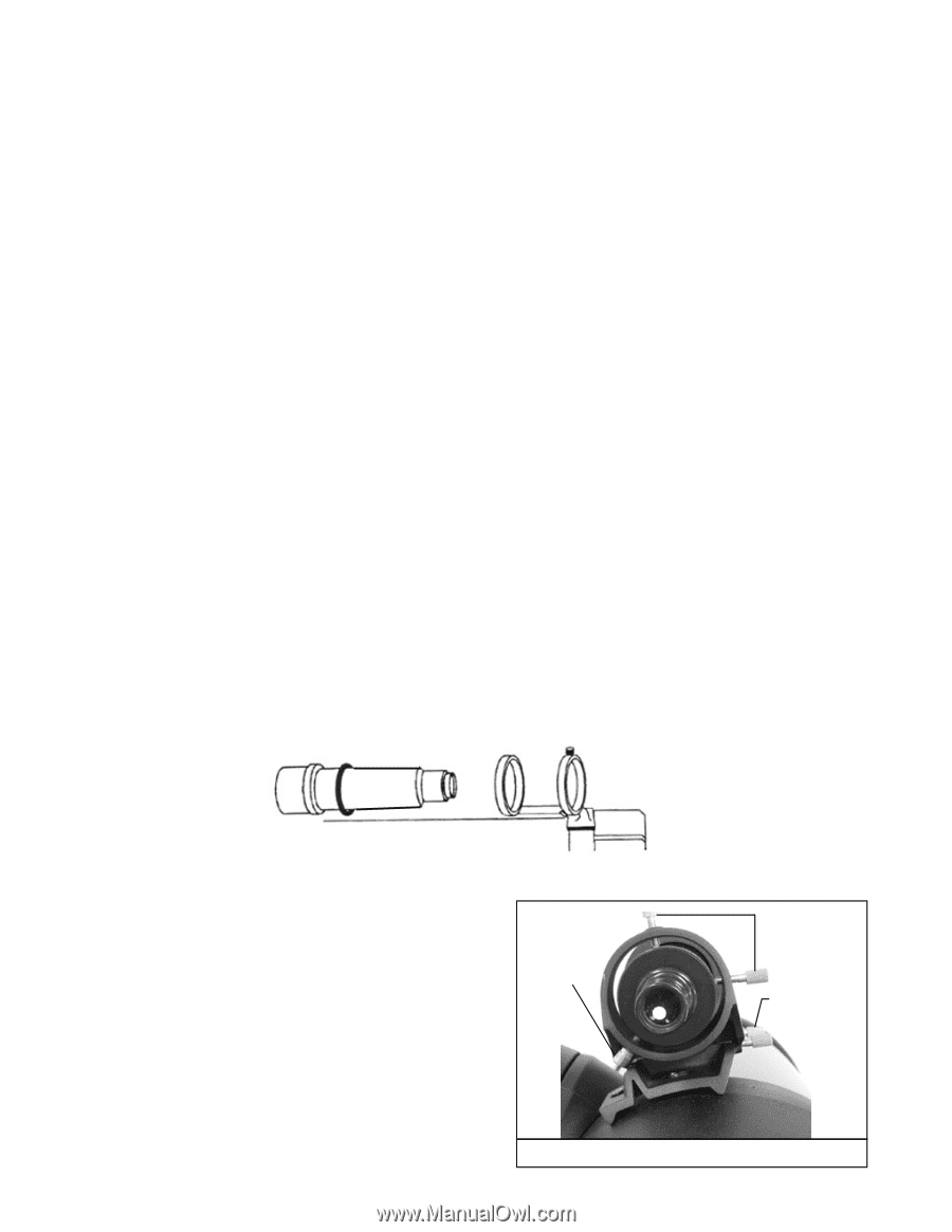
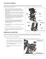
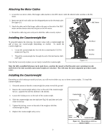
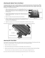
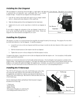
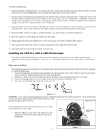
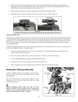
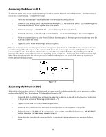
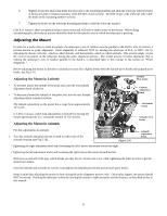
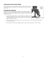
To install the finderscope: 1. Attach the bracket to the optical tube. To do this, place the curved portion of the bracket with the slot over the two holes in the rear cell. Start threading the screws in by hand and tighten fully with an Allen wrench. 2. Partially thread-in the three nylon thumbscrews that hold the finder in place inside the bracket. Tighten the screws until the nylon heads are flush with the inner diameter of the bracket ring. Do NOT thread them in completely or they will interfere with the placement of the finder. (Having the screws in place when the finder is installed will be easier than trying to insert the screws after the finder has been installed.) 3. Slide the rubber O-ring over the back of the finder (it will NOT fit over the objective end of the finder). It may need to be stretched a little. Once on the main body of the finder, slide it up about one inch from the end of the finder. 4. Rotate the finder until one cross hair is parallel to the R.A. axis and the other is parallel to the DEC axis. 5. Slide the eyepiece end of the finder into the front of the bracket. 6. Slightly tighten the three nylon thumbscrews on the front ring of the bracket to hold the finder in place. 7. Once on, push the finder back until the O-ring is snug inside the back ring of the finder bracket. 8. Hand tighten the three nylon tipped thumbscrews until snug. Installing the CGE Pro 1100 & 1400 Finderscope The CGE Pro 1100 and 1400 telescope comes with a 9x50 finderscope. The specifications for a finderscope stand for the magnification and the aperture, in millimeters, of the scope. So, a 9x50 finder magnifies objects nine times and has a 50mm objective lens. Finderscope Installation The finderscope must first be mounted in the included quick-release bracket then attached to the rear cell of the telescope. To install the finderscope: 1. Locate the finderscope mounting bracket attached to the bottom portion of the finder bracket. Loosen the two thumb screws to slide the mounting bracket from the finderscope bracket. 2. Find the two holes in the rear cell of the telescope on the top left, when looking from the back of the tube. 3. Place the mounting bracket over the two holes of the rear cell as shown in the figure 2-10. 4. Insert the screws through the bracket and into the rear cell. Figure 2-11 WARNING: If you remove the mounting bracket, do not completely thread the screws back into the rear cell of the telescope. The screws may be long enough to obstruct the movement of, and possibly damage the primary mirror. Alignment Screws With the bracket firmly attached to the telescope, you are ready to attach the finder to the bracket. 1. Slide the O-Ring over the back of the finderscope and position it on the tube toward the objective end of the finderscope. Pivot Screw Quick release Screws Figure 2-12 12
-
 1
1 -
2
-
3
-
4
-
5
-
6
-
 7
7 -
 8
8 -
 9
9 -
 10
10 -
 11
11 -
 12
12 -
 13
13 -
 14
14 -
 15
15 -
 16
16 -
 17
17 -
18
-
19
-
20
-
21
-
22
-
23
-
24
-
25
-
26
-
27
-
28
-
29
-
30
-
31
-
32
-
33
-
34
-
35
-
36
-
37
-
38
-
39
-
40
-
41
-
42
-
43
-
44
-
45
-
46
-
47
-
48
-
49
-
50
-
51
-
52
-
53
-
54
-
55
-
56
-
57
-
58
-
59
-
60
-
61
-
62
-
63
-
64
-
65
-
66
-
67
-
68
-
69
-
70
-
71
-
72
 |
 |