Chamberlain B373 B353 B353C B550 B550C B750 B750C B751C B970 B970C B1381 B1381 - Page 12
Electrical and Wiring 10 - Permanent Wiring
 |
View all Chamberlain B373 manuals
Add to My Manuals
Save this manual to your list of manuals |
Page 12 highlights
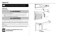
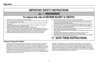
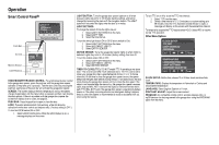
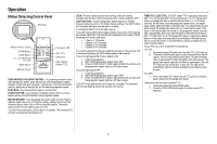
Electrical and Wiring For typical wiring, see Electrical and Wiring step 10 in the Installation Manual. Electrical and Wiring 10 - Permanent Wiring To prevent possible SERIOUS INJURY or DEATH from electrocution or fire: l Be sure power is NOT connected to the opener, and disconnect power to circuit BEFORE removing cover to establish permanent wiring connection. l Garage door installation and wiring MUST be in compliance with ALL local electrical and building codes. l NEVER use an extension cord, 2-wire adapter, or change plug in ANY way to make it fit outlet. Be sure the opener is grounded. To align the safety reversing sensors, see Electrical and Wiring step 13 in the Installation Manual. If LEDs are still flashing or not glowing, follow the directions below. Electrical and Wiring 14 - Align the Safety Reversing Sensors The door will not close if the sensors have not been installed and aligned correctly. The LEDs in both sensors will glow steadily if they are aligned and wired correctly. If the amber LED on the sending sensor is not glowing: 1. Make sure there is power to the garage door opener. 2. Make sure the sensor wire is not shorted/broken. 3. Make sure the sensor has been wired correctly: white wires to white terminal and white/black wires to grey terminal. 1 2 3 RED WHITE WHITE GREY If permanent wiring is required by your local code, refer to the following procedure. To make a permanent connection through the 7/8-inch hole in the top of the motor unit (according to local code): 1. Remove the motor unit cover screws and set the cover aside. 2. Remove the attached 3-prong cord. 3. Connect the black (line) wire to the screw on the brass terminal; the white (neutral) wire to the screw on the silver terminal; and the ground wire to the green ground screw. The opener must be grounded. 4. Reinstall the cover. Green Ground Screw Ground Tab Ground Wire White Wire Black Wire If the green LED on the receiving sensor is not glowing: 1. Make sure the sensor wire is not shorted/broken. 2. Make sure the sensors are aligned. 1 2 To continue, go to Electrical and Wiring step 11 in the Installation Manual To continue, go to Electrical and Wiring step 15 in the Installation Manual 12
-
 1
1 -
2
-
3
-
4
-
5
-
6
-
 7
7 -
 8
8 -
 9
9 -
 10
10 -
 11
11 -
 12
12 -
 13
13 -
 14
14 -
 15
15 -
 16
16 -
 17
17 -
18
-
19
-
20
-
21
-
22
-
23
-
24
-
25
-
26
-
27
-
28
-
29
-
30
-
31
-
32
-
33
-
34
-
35
-
36
-
37
-
38
-
39
-
40
-
41
-
42
-
43
-
44
-
45
-
46
-
47
-
48
-
49
-
50
-
51
-
52
-
53
-
54
-
55
-
56
-
57
-
58
-
59
-
60
-
61
-
62
-
63
-
64
-
65
-
66
-
67
-
68
-
69
-
70
-
71
-
72
 |
 |
