Cisco 1252G Hardware Installation Guide - Page 49
Connecting to an Ethernet Network with an Inline Power Source - ap
 |
UPC - 882658140631
View all Cisco 1252G manuals
Add to My Manuals
Save this manual to your list of manuals |
Page 49 highlights
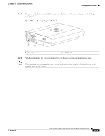
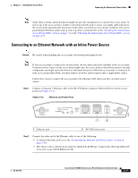
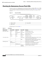
Chapter 2 Installing the Access Point Connecting the Ethernet and Power Cables Note Some older switches and patch panels might not provide enough power to operate the access point. At power-up, if the access point is unable to determine that the power source can supply sufficient power, the access point automatically deactivates both radios to prevent an over-current condition. The access point Status LED turns amber and an error log entry is created (refer to the "Checking the Autonomous Access Point LEDs" section on page 3-2 or the "Checking the Lightweight Access Point LEDs" section on page 4-3). Connecting to an Ethernet Network with an Inline Power Source Caution Be careful when handling the access point; the bottom plate might be hot. Note If your access point is connected to in-line power, do not connect the power module to the access point. Using two power sources on the access point might cause the access point to shut down to protect internal components and might cause the switch to shut down the port to which the access point is connected. If your access point shuts down, you must remove all power and reconnect only a single power source. Follow these steps to connect the access point to the Ethernet LAN when you have an inline power source: Step 1 Connect a Category 5 Ethernet cable to the RJ-45 Ethernet connector labeled Ethernet on the access point (see Figure 2-13). Figure 2-13 Ethernet and Power Ports 135494 2.4 GHz LEFT STATUS RADIO ETHERNET CONSOLE MODE ETHERNET 48VDC 2.4 GHz RIGHT/PRIMARY 1 2 1 Ethernet port 2 48 VDC power port Step 2 Connect the other end of the Ethernet cable to one of the following: • A switch with inline power (see the "Connecting the Ethernet and Power Cables" section on page 2-20). • The end of a Cisco Aironet power injector labeled To AP/Bridge. Connect the other end labeled To Network to your 10/100 Ethernet LAN. OL-8371-05 Cisco Aironet 1240AG Series Access Point Hardware Installation Guide 2-21
-
 1
1 -
2
-
3
-
4
-
5
-
6
-
7
-
8
-
9
-
10
-
11
-
12
-
13
-
14
-
15
-
16
-
17
-
18
-
19
-
20
-
21
-
22
-
23
-
24
-
25
-
26
-
27
-
28
-
29
-
30
-
31
-
32
-
33
-
34
-
35
-
36
-
37
-
38
-
39
-
40
-
41
-
42
-
43
-
 44
44 -
 45
45 -
 46
46 -
 47
47 -
 48
48 -
 49
49 -
 50
50 -
 51
51 -
 52
52 -
 53
53 -
 54
54 -
55
-
56
-
57
-
58
-
59
-
60
-
61
-
62
-
63
-
64
-
65
-
66
-
67
-
68
-
69
-
70
-
71
-
72
-
73
-
74
-
75
-
76
-
77
-
78
-
79
-
80
-
81
-
82
-
83
-
84
-
85
-
86
-
87
-
88
-
89
-
90
-
91
-
92
-
93
-
94
-
95
-
96
-
97
-
98
-
99
-
100
-
101
-
102
-
103
-
104
-
105
-
106
-
107
-
108
-
109
-
110
-
111
-
112
-
113
-
114
-
115
-
116
-
117
-
118
-
119
-
120
-
121
-
122
-
123
-
124
 |
 |
