Cisco 2960G-48TC Hardware Installation Guide - Page 42
Cisco RPS Connector, RPS Connector on the Catalyst 2912 XL, 2924C XL, and 2924M XL Switches - specifications
 |
UPC - 882658036590
View all Cisco 2960G-48TC manuals
Add to My Manuals
Save this manual to your list of manuals |
Page 42 highlights
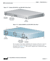
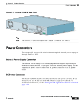
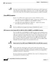
Power Connectors Chapter 1 Product Overview Caution You must connect the Catalyst 2924M XL DC switch only to a DC-input power source that has an input supply voltage from -36 to -72 VDC. If the supply voltage is not in this range, the switch might not operate properly or might be damaged. Cisco RPS Connector Specific Cisco RPS models support specific Catalyst 2900 XL switches: • Cisco RPS 600 (model PWR600-AC-RPS)-supports the Catalyst 2912 XL, 2924C XL, 2924 XL, 2924MF XL, and 2924M XL switches. • Cisco RPS 300 (model PWR300-AC-RPS-N1)-supports the Catalyst 2912 LRE XL and 2924 LRE XL switches Note The Cisco RPS does not support the Catalyst 2924M XL DC switch. RPS Connector on the Catalyst 2912 XL, 2924C XL, 2924 XL, 2924MF XL, and 2924M XL Switches The Cisco RPS 600 (model PWR600-AC-RPS) provides a quasi-redundant power source for four external devices that use up to 150W DC each. Use a one-to-one cable (one connector at each cable end) to connect four external devices to the four DC output power modules. The power source is quasi-redundant because there are two AC input power modules for the Cisco RPS and one DC output power module for each external device. The AC input to the Cisco RPS is fully redundant, but the DC output to the external devices is not. Warning Attach only the Cisco RPS (model PWR600-AC-RPS) to the RPS 600 receptacle. Note Do not connect the switch power cord to an AC outlet if the switch is also connected to a powered-on RPS. The switches do not support the fully-redundant configuration described in the RPS documentation. We do not recommend the redundant-with-reboot configuration. For more information on the Cisco RPS 600, refer to the Cisco Redundant Power System Hardware Installation Guide. 1-22 Catalyst 2900 Series XL Hardware Installation Guide 78-6461-04
-
 1
1 -
2
-
3
-
4
-
5
-
6
-
7
-
8
-
9
-
10
-
11
-
12
-
13
-
14
-
15
-
16
-
17
-
18
-
19
-
20
-
21
-
22
-
23
-
24
-
25
-
26
-
27
-
28
-
29
-
30
-
31
-
32
-
33
-
34
-
35
-
36
-
 37
37 -
 38
38 -
 39
39 -
 40
40 -
 41
41 -
 42
42 -
 43
43 -
 44
44 -
 45
45 -
 46
46 -
 47
47 -
48
-
49
-
50
-
51
-
52
-
53
-
54
-
55
-
56
-
57
-
58
-
59
-
60
-
61
-
62
-
63
-
64
-
65
-
66
-
67
-
68
-
69
-
70
-
71
-
72
-
73
-
74
-
75
-
76
-
77
-
78
-
79
-
80
-
81
-
82
-
83
-
84
-
85
-
86
-
87
-
88
-
89
-
90
-
91
-
92
-
93
-
94
-
95
-
96
-
97
-
98
-
99
-
100
-
101
-
102
-
103
-
104
-
105
-
106
-
107
-
108
-
109
-
110
-
111
-
112
-
113
-
114
-
115
-
116
-
117
-
118
-
119
-
120
-
121
-
122
-
123
-
124
-
125
-
126
-
127
-
128
-
129
-
130
-
131
-
132
-
133
-
134
-
135
-
136
-
137
-
138
-
139
-
140
-
141
-
142
-
143
-
144
-
145
-
146
-
147
-
148
-
149
-
150
-
151
-
152
-
153
-
154
-
155
-
156
-
157
-
158
-
159
-
160
-
161
-
162
 |
 |
