Cisco 6941 Administration Guide - Page 176
E-3, Attaching the Phone Bracket, Step 2 - handset cord
 |
UPC - 882658277801
View all Cisco 6941 manuals
Add to My Manuals
Save this manual to your list of manuals |
Page 176 highlights
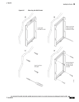
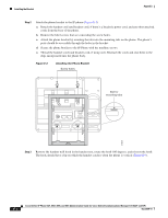
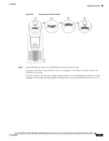
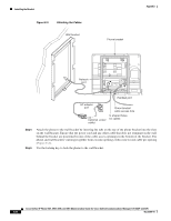
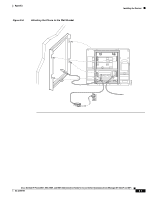
Installing the Bracket Appendix Step 2 Attach the phone bracket to the IP phone (Figure E-3). a. Detach the handset cord (and headset cord, if there is a headset), power cord, and any other attached cords from the base of the phone. b. Remove the label covers that are concealing the screw holes. c. Attach the phone bracket by inserting the tabs into the mounting tabs on the phone. The phone's ports should be accessible through the holes in the bracket. d. Secure the phone bracket to the IP Phone with the machine screws. e. Thread the handset cord (and headset cord, if using one). Reattach the cords and seat them in the clips incorporated into the phone body. Figure E-3 Attaching the Phone Bracket Screw holes Slot for mounting tabs 274937 Step 3 Remove the handset wall hook in the handset rest, rotate the hook 180 degrees, and reinsert the hook. The hook should have a lip on which the handset catches when the phone is vertical (Figure E-4). Cisco Unified IP Phone 6921, 6941, 6945, and 6961 Administration Guide for Cisco Unified Communications Manager 8.5 (SCCP and SIP) E-4 OL-23769-01
-
 1
1 -
2
-
3
-
4
-
5
-
6
-
7
-
8
-
9
-
10
-
11
-
12
-
13
-
14
-
15
-
16
-
17
-
18
-
19
-
20
-
21
-
22
-
23
-
24
-
25
-
26
-
27
-
28
-
29
-
30
-
31
-
32
-
33
-
34
-
35
-
36
-
37
-
38
-
39
-
40
-
41
-
42
-
43
-
44
-
45
-
46
-
47
-
48
-
49
-
50
-
51
-
52
-
53
-
54
-
55
-
56
-
57
-
58
-
59
-
60
-
61
-
62
-
63
-
64
-
65
-
66
-
67
-
68
-
69
-
70
-
71
-
72
-
73
-
74
-
75
-
76
-
77
-
78
-
79
-
80
-
81
-
82
-
83
-
84
-
85
-
86
-
87
-
88
-
89
-
90
-
91
-
92
-
93
-
94
-
95
-
96
-
97
-
98
-
99
-
100
-
101
-
102
-
103
-
104
-
105
-
106
-
107
-
108
-
109
-
110
-
111
-
112
-
113
-
114
-
115
-
116
-
117
-
118
-
119
-
120
-
121
-
122
-
123
-
124
-
125
-
126
-
127
-
128
-
129
-
130
-
131
-
132
-
133
-
134
-
135
-
136
-
137
-
138
-
139
-
140
-
141
-
142
-
143
-
144
-
145
-
146
-
147
-
148
-
149
-
150
-
151
-
152
-
153
-
154
-
155
-
156
-
157
-
158
-
159
-
160
-
161
-
162
-
163
-
164
-
165
-
166
-
167
-
168
-
169
-
170
-
 171
171 -
 172
172 -
 173
173 -
 174
174 -
 175
175 -
 176
176 -
 177
177 -
 178
178 -
 179
179 -
 180
180 -
 181
181 -
182
-
183
-
184
-
185
-
186
-
187
-
188
-
189
-
190
-
191
-
192
-
193
-
194
-
195
-
196
 |
 |
